Automatic Room Light Controller Using Arduino | DIY Smart Light Project
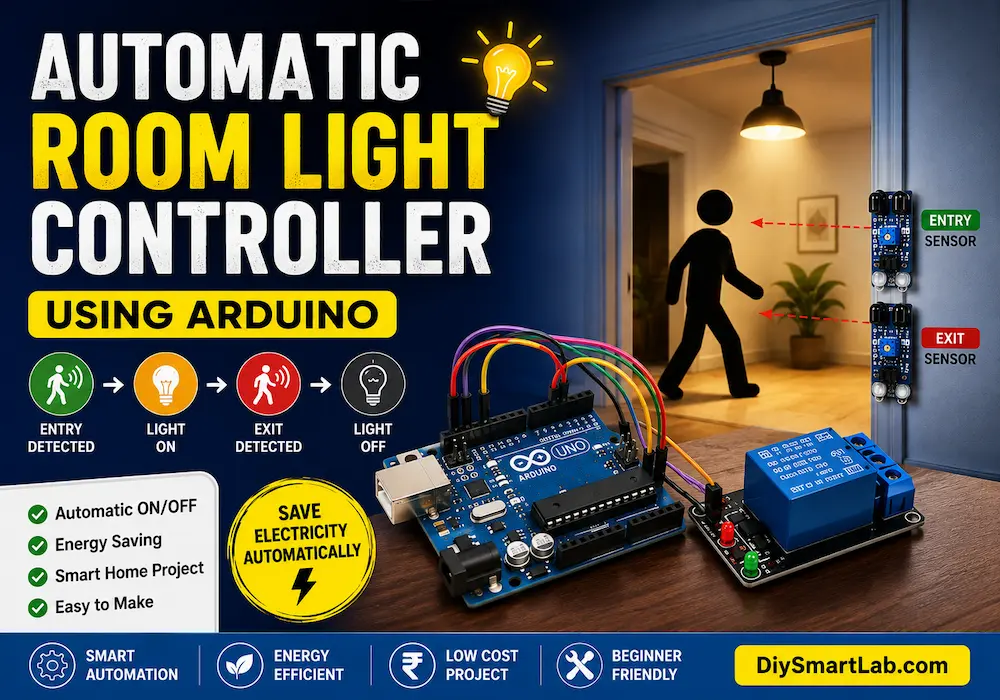
Automatic Room Light Controller Using Arduino
An Automatic Room Light Controller Using Arduino is a smart DIY electronics project that automatically turns lights ON or OFF when a person enters or leaves a room. This project is widely used in smart homes, offices, classrooms, and energy-saving automation systems. In this tutorial by DiySmartLab.com, you will learn the complete working principle, circuit diagram, components list, Arduino code, applications, and advantages of this smart lighting system.
What is an Automatic Room Light Controller?
An Automatic Room Light Controller is an intelligent lighting system that detects human movement and controls room lights automatically. The system uses sensors connected to an Arduino board to detect entry or exit. When someone enters the room, the light turns ON automatically, and when everyone leaves, the light turns OFF.
This project helps save electricity and is a perfect beginner-friendly Arduino automation project.
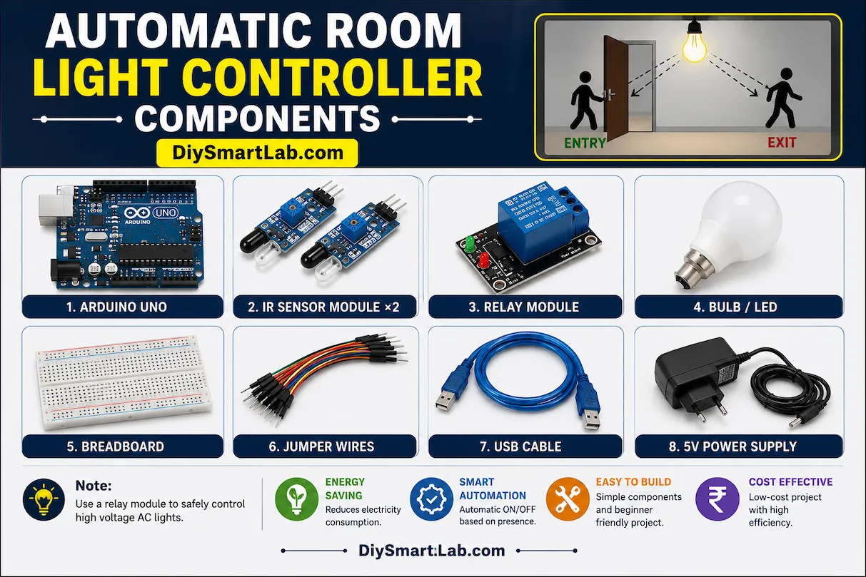
Components Required
- Arduino Uno
- IR Sensor Module ×2
- Relay Module
- Bulb or LED
- Breadboard
- Jumper Wires
- USB Cable
- 5V Power Supply
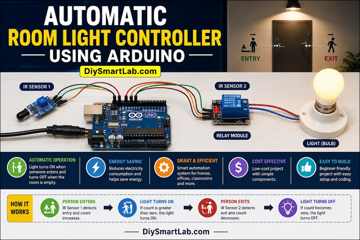
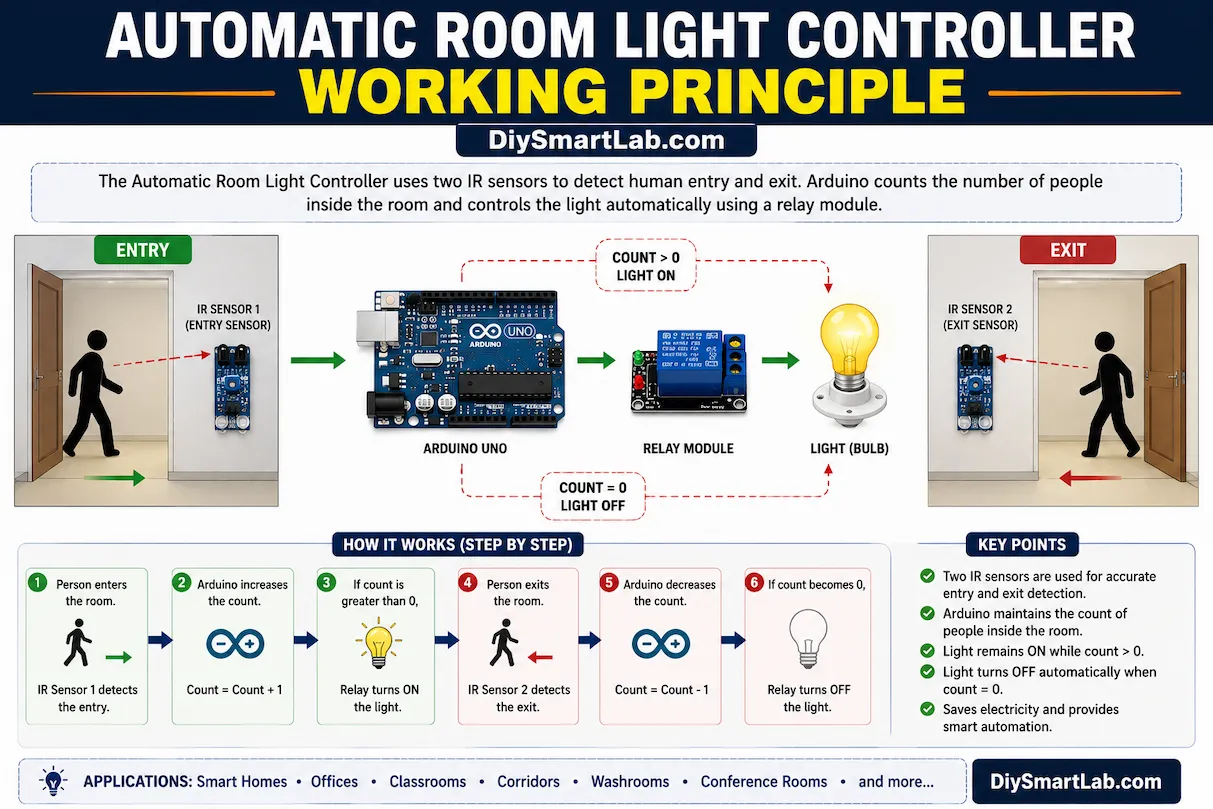
How Automatic Room Light Controller Works
The working principle of this project is very simple. Two IR sensors are placed at the door. One sensor detects entry while the other detects exit. The Arduino counts the number of people inside the room.
- When a person enters the room, the count increases.
- When a person exits the room, the count decreases.
- If the count is greater than zero, the light remains ON.
- If the count becomes zero, the Arduino turns OFF the light automatically.
This smart automation system helps reduce unnecessary electricity consumption.
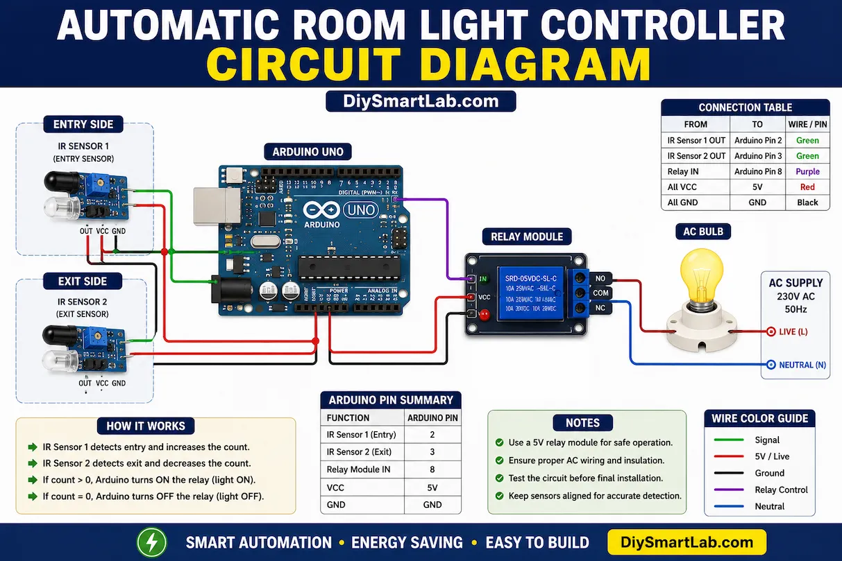
Automatic Room Light Controller Circuit Diagram
Connect the IR sensors and relay module to the Arduino Uno according to the circuit below:
- IR Sensor 1 Output → Arduino Pin 2
- IR Sensor 2 Output → Arduino Pin 3
- Relay IN → Arduino Pin 8
- Relay VCC → 5V
- Relay GND → GND
- Light/Bulb connected through relay
Arduino Code for Automatic Room Light Controller
int sensor1 = 2;
int sensor2 = 3;
int relay = 8;

int count = 0;

void setup() {
  pinMode(sensor1, INPUT);
  pinMode(sensor2, INPUT);
  pinMode(relay, OUTPUT);

  digitalWrite(relay, LOW);
}

void loop() {

  if(digitalRead(sensor1) == LOW) {
    count++;
    delay(1000);
  }

  if(digitalRead(sensor2) == LOW) {
    count--;
    delay(1000);
  }

  if(count > 0) {
    digitalWrite(relay, HIGH);
  } else {
    digitalWrite(relay, LOW);
    count = 0;
  }
}
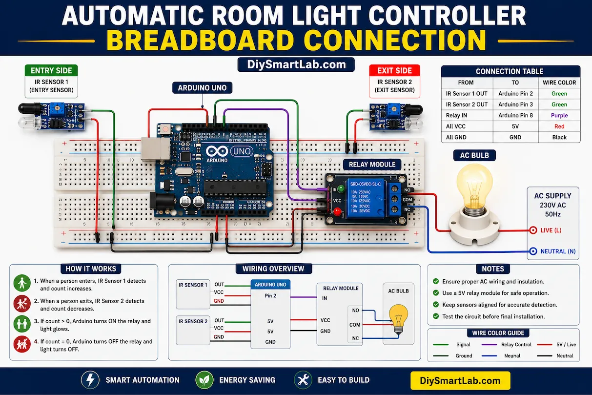
Automatic Room Light Controller Breadboard Connection
The breadboard setup is easy and beginner-friendly. Place the Arduino Uno in the center and connect both IR sensors on either side of the breadboard. Connect the relay module output to the bulb circuit carefully.
Important: Be careful while handling AC bulbs and relay modules. Always switch OFF the main power before wiring.
Advantages of Automatic Room Light Controller
- Saves electricity automatically
- Reduces human effort
- Smart home automation project
- Easy to build using Arduino
- Low-cost automation solution
- Improves energy efficiency
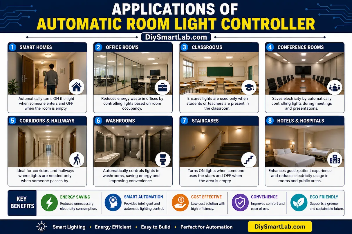
Applications of Automatic Room Light Controller
- Smart homes
- Office rooms
- Classrooms
- Conference halls
- Corridors
- Washrooms
- Energy-saving lighting systems
Tips for Better Performance
- Place IR sensors properly for accurate detection
- Avoid direct sunlight on IR sensors
- Use proper relay insulation for safety
- Test sensor distance before installation
- Use a stable 5V power supply
Conclusion
The Automatic Room Light Controller Using Arduino is an excellent smart automation project for beginners and electronics enthusiasts. It demonstrates how Arduino and sensors can be used to build intelligent energy-saving systems. This project is affordable, easy to build, and highly useful for home automation applications.
For more Arduino projects, electronics tutorials, and smart DIY ideas, visit DiySmartLab.com.
Frequently Asked Questions (FAQs)
Can I use a PIR sensor instead of an IR sensor?
Yes, you can use a PIR sensor for motion detection, but IR sensors provide better entry and exit counting.
Is this project safe for AC bulbs?
Yes, but you must use relay modules carefully and follow electrical safety precautions.
Can I make this project wireless?
Yes, you can upgrade this project using ESP8266 or ESP32 for WiFi-based smart home automation.