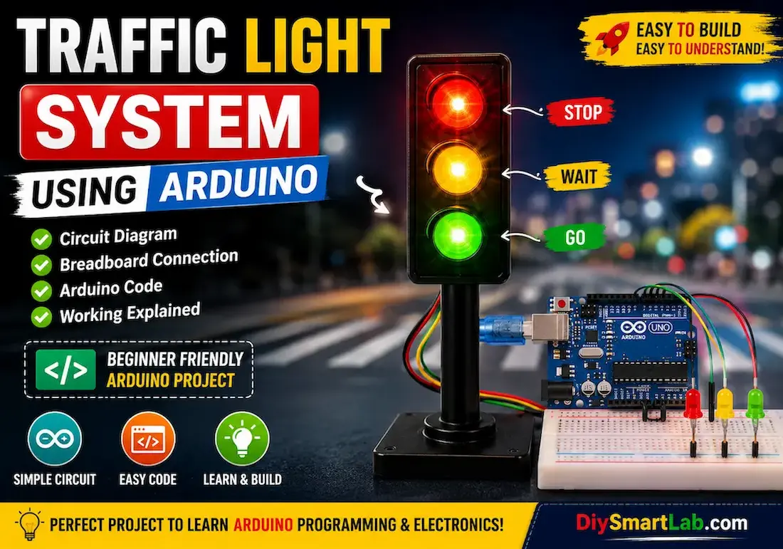
RGB LED Control Using Arduino | Beginner Arduino RGB LED Project
RGB LED Control Using Arduino – Beginner Friendly Arduino RGB LED Project
Learning how to control an RGB LED using Arduino is one of the best beginner electronics projects for understanding PWM (Pulse Width Modulation), color mixing, and LED control. In this tutorial by DiySmartLab.com, you will learn how an RGB LED works, how to connect it with Arduino Uno, complete circuit diagram, Arduino code, and practical applications.
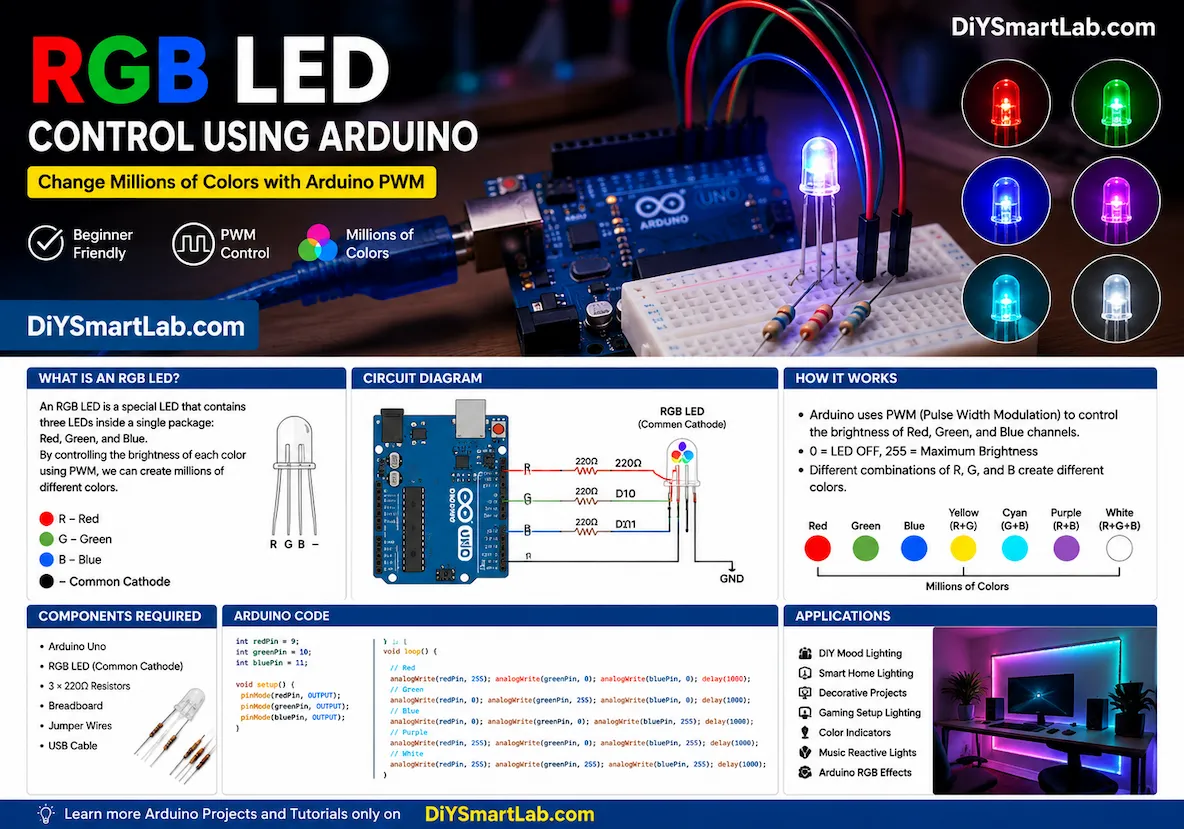
What is an RGB LED?
An RGB LED is a special type of LED that contains three different LEDs inside a single package:
- Red LED
- Green LED
- Blue LED
By controlling the brightness of these three colors individually, you can create millions of different colors. Arduino uses PWM pins to control the brightness levels of Red, Green, and Blue channels.
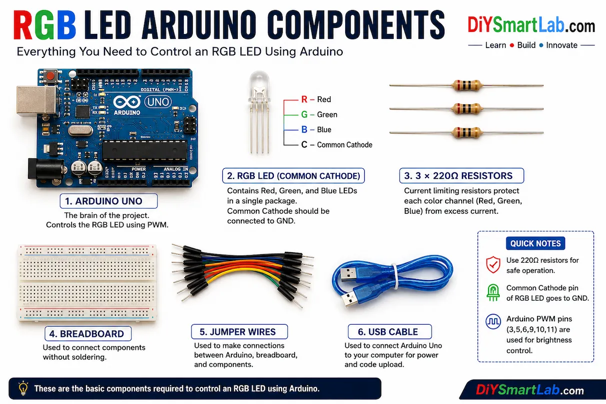
Components Required for RGB LED Arduino Project
- Arduino Uno
- RGB LED (Common Cathode)
- 3 × 220Ω Resistors
- Breadboard
- Jumper Wires
- USB Cable
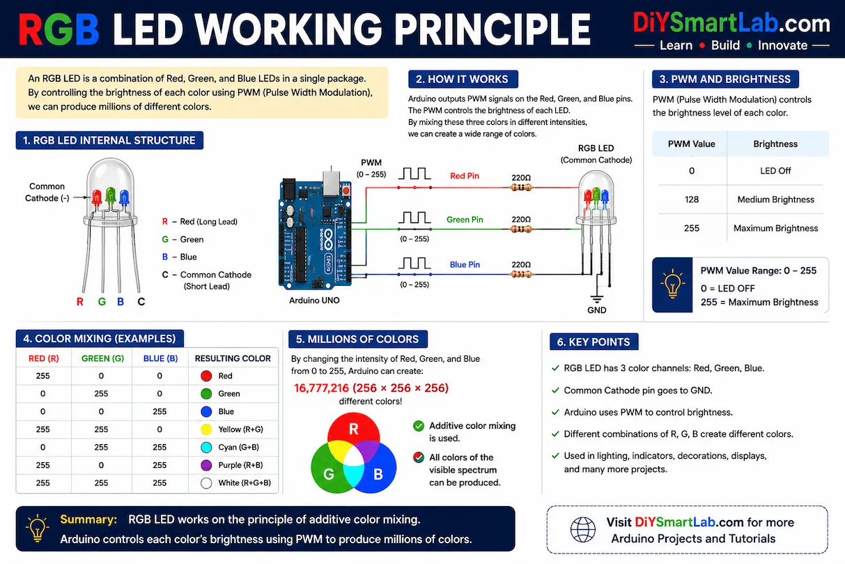
How RGB LED Works
An RGB LED mixes Red, Green, and Blue light to produce different colors. Arduino sends PWM signals to the RGB LED pins, controlling the brightness of each color.
For example:
- Red + Green = Yellow
- Red + Blue = Purple
- Green + Blue = Cyan
- Red + Green + Blue = White
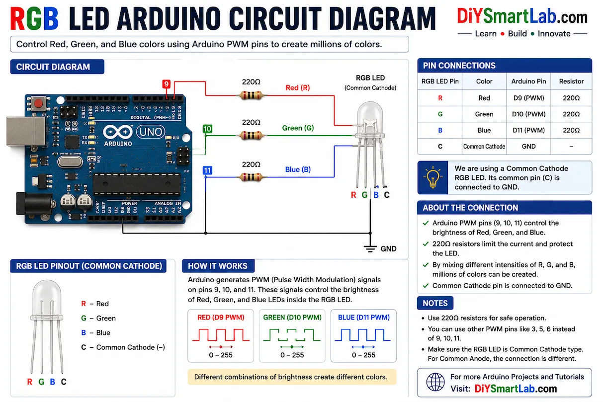
RGB LED Arduino Circuit Diagram
Connect the RGB LED pins to Arduino PWM pins using current limiting resistors.
- Red Pin → Arduino Pin 9
- Green Pin → Arduino Pin 10
- Blue Pin → Arduino Pin 11
- Common Cathode → GND
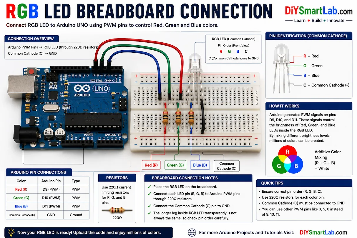
RGB LED Breadboard Connection
Insert the RGB LED on the breadboard carefully. Use three resistors between Arduino pins and RGB LED color pins to protect the LED from excess current.
Arduino Code for RGB LED Control
int redPin = 9;
int greenPin = 10;
int bluePin = 11;

void setup()
{
  pinMode(redPin, OUTPUT);
  pinMode(greenPin, OUTPUT);
  pinMode(bluePin, OUTPUT);
}

void loop()
{
  // Red Color
  analogWrite(redPin, 255);
  analogWrite(greenPin, 0);
  analogWrite(bluePin, 0);
  delay(1000);

  // Green Color
  analogWrite(redPin, 0);
  analogWrite(greenPin, 255);
  analogWrite(bluePin, 0);
  delay(1000);

  // Blue Color
  analogWrite(redPin, 0);
  analogWrite(greenPin, 0);
  analogWrite(bluePin, 255);
  delay(1000);

  // Purple Color
  analogWrite(redPin, 255);
  analogWrite(greenPin, 0);
  analogWrite(bluePin, 255);
  delay(1000);

  // White Color
  analogWrite(redPin, 255);
  analogWrite(greenPin, 255);
  analogWrite(bluePin, 255);
  delay(1000);
}
How the Arduino RGB LED Code Works
The Arduino uses analogWrite() function to generate PWM signals. PWM allows Arduino to control the brightness of each LED color.
- 0 = LED OFF
- 255 = Maximum Brightness
Different brightness combinations generate different colors.
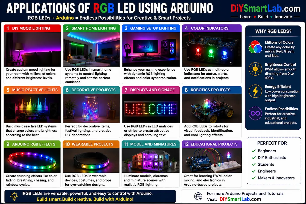
Applications of RGB LED Using Arduino
- DIY Mood Lighting
- Arduino Decorative Projects
- Smart Home Lighting
- Gaming Setup Lighting
- Color Indicators
- Music Reactive Lights
- Arduino RGB Effects
Common Problems and Solutions
- LED not glowing: Check wiring and resistor connections.
- Wrong colors: Verify RGB pin sequence.
- Dim light: Use proper PWM values.
- Arduino not detecting: Select correct COM port and board.
Conclusion
RGB LED Control Using Arduino is an excellent beginner-friendly electronics project that teaches PWM control, LED interfacing, and color mixing concepts. After learning this project, you can create advanced Arduino lighting systems, smart home projects, and beautiful RGB effects.
Frequently Asked Questions (FAQs)
Can I use a common anode RGB LED?
Yes, but the logic will be reversed. LOW signal turns the LED ON.
Why are resistors required?
Resistors limit current and protect the RGB LED from damage.
Which Arduino pins support PWM?
Arduino Uno PWM pins are 3, 5, 6, 9, 10, and 11.
Can I create custom colors?
Yes, by changing PWM values of Red, Green, and Blue channels.