IoT Weather Monitoring System by ESP8266 – Complete DIY Guide
IoT Weather Monitoring System by ESP8266: Complete Beginner-Friendly Guide
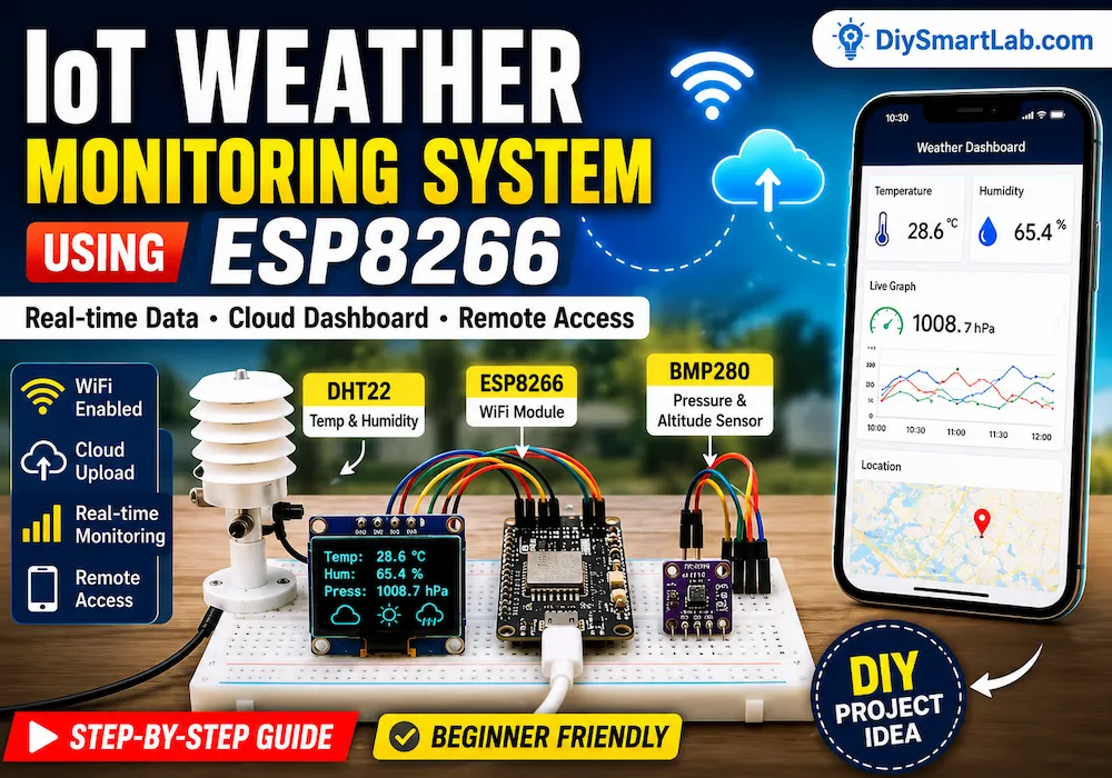
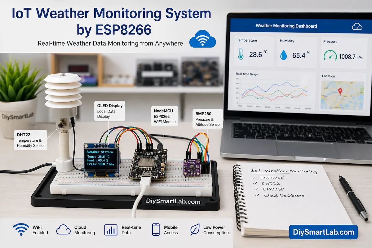
An IoT Weather Monitoring System by ESP8266 is one of the most popular DIY electronics projects for beginners. It allows you to monitor environmental conditions such as temperature, humidity, and atmospheric pressure in real time from anywhere using the internet.
With the help of the ESP8266 WiFi module and weather sensors, you can create a smart weather station that sends live data to your smartphone, laptop, or cloud dashboard.
In this detailed guide by DiySmartLab.com, you will learn how the IoT Weather Monitoring System by ESP8266 works, required components, circuit connections, applications, advantages, disadvantages, and frequently asked questions.
What is an IoT Weather Monitoring System?
An IoT Weather Monitoring System is a smart electronic system that collects weather-related data using sensors and uploads the information to the internet.
Unlike traditional weather stations, IoT-based systems allow users to access data remotely through cloud platforms, mobile applications, or web dashboards.
The ESP8266 microcontroller makes this possible because it has built-in WiFi connectivity.
Features of IoT Weather Monitoring System by ESP8266
- Real-time weather monitoring
- Built-in WiFi connectivity
- Remote access through internet
- Cloud data storage
- Low power consumption
- Easy integration with sensors
- Smartphone and web dashboard support
- Low-cost implementation
- Suitable for home and industrial use
- Expandable for future upgrades
Why Use ESP8266 for Weather Monitoring?
The ESP8266 is one of the most widely used IoT development boards. It combines a microcontroller and WiFi module into a single compact device.
Therefore, it becomes an ideal choice for weather monitoring projects.
| Feature | ESP8266 Benefit |
|---|---|
| WiFi Connectivity | Built-in internet access |
| Cost | Very affordable |
| Programming | Arduino IDE compatible |
| Power Consumption | Low power operation |
| GPIO Pins | Supports multiple sensors |
| Community Support | Large number of tutorials |
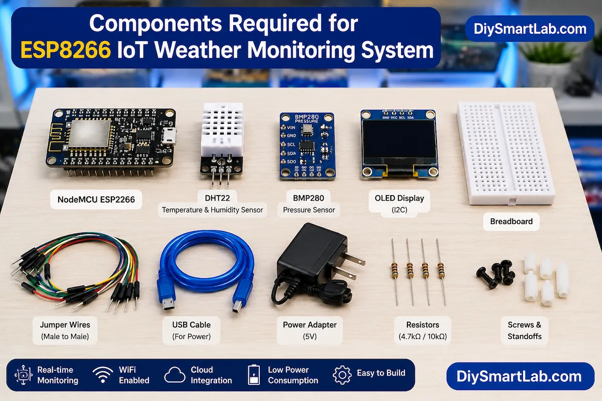
Main Components Required
The following components are commonly used in an IoT Weather Monitoring System by ESP8266.
| Component | Purpose |
|---|---|
| NodeMCU ESP8266 | Main controller with WiFi |
| DHT22 Sensor | Temperature and humidity measurement |
| BMP280 Sensor | Atmospheric pressure measurement |
| OLED Display | Local data display |
| Breadboard | Prototype assembly |
| Jumper Wires | Electrical connections |
| USB Cable | Programming and power supply |
| Power Source | System operation |
Understanding the Sensors
DHT22 Temperature and Humidity Sensor
The DHT22 sensor measures ambient temperature and humidity.
It provides better accuracy than the DHT11 sensor and works well for weather station projects.
BMP280 Pressure Sensor
The BMP280 sensor measures atmospheric pressure and altitude.
This sensor improves the functionality of the weather station by providing additional environmental data.
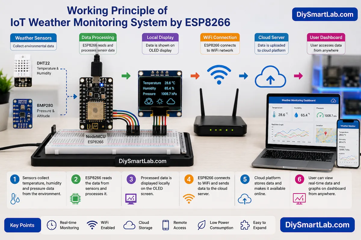
Working Principle of IoT Weather Monitoring System by ESP8266
The working process is simple and beginner-friendly.
- Sensors collect environmental data.
- ESP8266 reads sensor values.
- The controller processes the data.
- Data is displayed on the OLED screen.
- ESP8266 connects to WiFi.
- Weather information is uploaded to a cloud server.
- Users access live data remotely.
This continuous cycle creates a smart weather monitoring system.
Block Diagram Explanation
The IoT weather monitoring system consists of several interconnected modules.
- DHT22 Sensor → Temperature & Humidity
- BMP280 Sensor → Pressure Measurement
- ESP8266 NodeMCU → Data Processing
- OLED Display → Local Visualization
- WiFi Router → Internet Connectivity
- Cloud Platform → Data Storage
- User Dashboard → Remote Monitoring
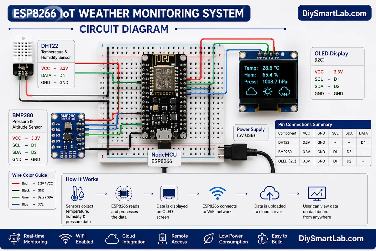
Circuit Explanation
The circuit is simple and suitable for beginners.
DHT22 Connections
| DHT22 Pin | NodeMCU Pin |
|---|---|
| VCC | 3.3V |
| GND | GND |
| DATA | D4 (GPIO2) |
BMP280 Connections
| BMP280 Pin | NodeMCU Pin |
|---|---|
| VIN | 3.3V |
| GND | GND |
| SCL | D1 (GPIO5) |
| SDA | D2 (GPIO4) |
OLED Display Connections
| OLED Pin | NodeMCU Pin |
|---|---|
| VCC | 3.3V |
| GND | GND |
| SCL | D1 |
| SDA | D2 |
How Data Reaches the Cloud
After collecting weather information, the ESP8266 connects to a WiFi network.
Next, it sends the data to cloud services such as:
- ThingSpeak
- Blynk IoT
- Arduino IoT Cloud
- Firebase
- AWS IoT
- Custom Web Server
As a result, users can view live weather information from any location.
Programming Overview
The ESP8266 can be programmed using Arduino IDE.
The software performs the following tasks:
- Connects to WiFi
- Reads sensor values
- Processes environmental data
- Updates OLED display
- Uploads data to cloud platform
- Refreshes information periodically
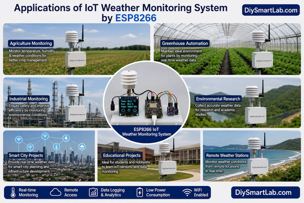
Applications of IoT Weather Monitoring System by ESP8266
This project has many practical applications.
- Home weather station
- Agriculture monitoring
- Greenhouse automation
- Industrial environment monitoring
- Research projects
- School and college projects
- Smart city infrastructure
- Weather forecasting systems
- Remote environmental monitoring
- IoT learning platform
Advantages of IoT Weather Monitoring System by ESP8266
- Low-cost implementation
- Remote access capability
- Real-time monitoring
- Easy cloud integration
- Low power consumption
- Simple installation
- Expandable design
- Suitable for beginners
- Wireless communication
- Open-source ecosystem
Disadvantages of IoT Weather Monitoring System by ESP8266
- Requires WiFi connectivity
- Sensor accuracy depends on quality
- Cloud services may have limitations
- Outdoor installations need weather protection
- Power backup may be required
- Internet outages affect remote monitoring
Future Improvements
You can improve this project further by adding additional sensors and smart features.
- Rain sensor
- Wind speed sensor
- Wind direction sensor
- Solar radiation sensor
- Battery backup system
- Solar charging capability
- Mobile application integration
- AI-based weather prediction
Frequently Asked Questions (FAQs)
Can beginners build an IoT Weather Monitoring System by ESP8266?
Yes. The project is beginner-friendly and requires only basic electronics knowledge.
Which sensor is better, DHT11 or DHT22?
DHT22 provides higher accuracy and a wider measurement range than DHT11.
Can I monitor weather data from my smartphone?
Yes. Cloud platforms allow remote monitoring through mobile apps and web dashboards.
Does ESP8266 have built-in WiFi?
Yes. ESP8266 includes integrated WiFi functionality.
Can I add more sensors?
Yes. Additional sensors such as rain, wind, and air quality sensors can be added easily.
Which cloud platform is best for beginners?
ThingSpeak and Blynk are excellent choices because they are easy to configure.
Conclusion
The IoT Weather Monitoring System by ESP8266 is an excellent project for learning IoT, cloud computing, and sensor interfacing. It provides real-time environmental monitoring while demonstrating the power of connected devices.
Because the ESP8266 includes built-in WiFi, the entire system remains affordable and easy to build. Furthermore, the project can be expanded with additional sensors and automation features.
Whether you are a student, hobbyist, or electronics enthusiast, this IoT Weather Monitoring System by ESP8266 is a valuable project to add to your DIY portfolio.
At DiySmartLab.com, we highly recommend this project for anyone who wants to start their journey into the exciting world of IoT and smart electronics.