
Series vs Parallel Circuits Explained: Difference, Examples & Uses
Series vs Parallel Circuits Explained – Complete Beginner Guide
Understanding series and parallel circuits is one of the most important basics in electronics and electrical engineering. Whether you are building an Arduino project, designing a DIY electronic circuit, or learning electrical fundamentals, knowing the difference between these two circuit types is essential.
In this beginner-friendly guide by DiySmartLab.com, you will learn what series and parallel circuits are, how they work, their advantages and disadvantages, real-world applications, and the major differences between them.
What is a Series Circuit?
A series circuit is a type of electrical circuit where all components are connected one after another in a single path. In this setup, electric current flows through each component sequentially.
If one component fails or disconnects, the entire circuit stops working because the current path breaks completely.
Characteristics of Series Circuits
- Only one path for current flow
- Same current flows through all components
- Total voltage is divided across components
- If one component fails, the whole circuit stops
- Easy to design and build
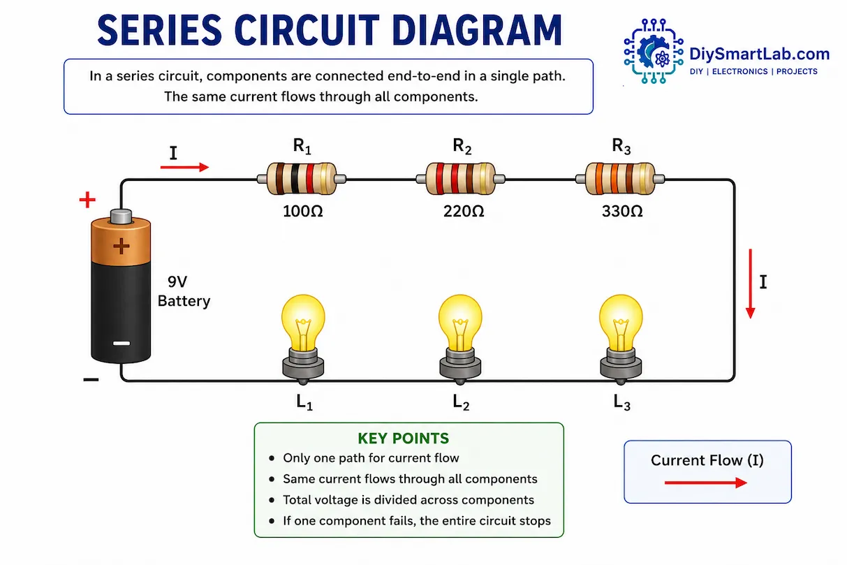
How Does a Series Circuit Work?
In a series circuit, electricity travels through one component and then moves to the next component in the same line. For example, if you connect three LEDs in series with a battery, the current flows through LED1, then LED2, and finally LED3.
If any one LED becomes damaged or disconnected, all LEDs turn OFF because the circuit path breaks.
What is a Parallel Circuit?
A parallel circuit is a circuit where components are connected across multiple paths or branches. Each branch receives the same voltage directly from the power source.
Unlike series circuits, if one component fails in a parallel circuit, the other components continue working normally.
Characteristics of Parallel Circuits
- Multiple paths for current flow
- Voltage is the same across all branches
- Current divides between branches
- One component failure does not affect others
- Commonly used in homes and electronics
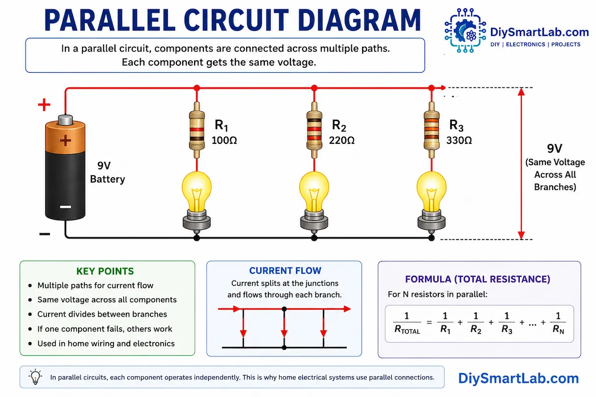
How Does a Parallel Circuit Work?
In a parallel circuit, each component has its own separate path connected to the power source. For example, if three bulbs are connected in parallel, every bulb receives full voltage independently.
If one bulb burns out, the remaining bulbs continue glowing because their paths remain complete.
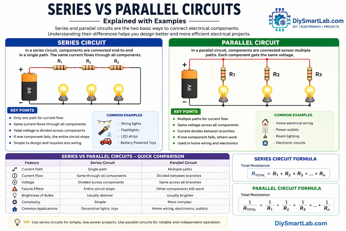
Series vs Parallel Circuits – Main Differences
| Feature | Series Circuit | Parallel Circuit |
|---|---|---|
| Current Path | Single path | Multiple paths |
| Current Flow | Same through all components | Divided between branches |
| Voltage | Divided across components | Same across all branches |
| Failure Effect | Entire circuit stops | Other components still work |
| Brightness of Bulbs | Usually dimmer | Usually brighter |
| Complexity | Simple | More complex |
| Common Applications | Decorative lights | Home wiring |
Advantages of Series Circuits
- Simple and easy to build
- Requires fewer wires
- Ideal for basic electronics learning
- Useful in low-cost circuits
Disadvantages of Series Circuits
- If one component fails, the entire circuit stops
- Voltage decreases across components
- Not suitable for home electrical systems
- Bulbs may appear dimmer
Advantages of Parallel Circuits
- Components work independently
- Full voltage available to each branch
- Reliable and efficient
- Perfect for household wiring systems
Disadvantages of Parallel Circuits
- Requires more wires
- More complicated to design
- Higher installation cost
- Current consumption can increase
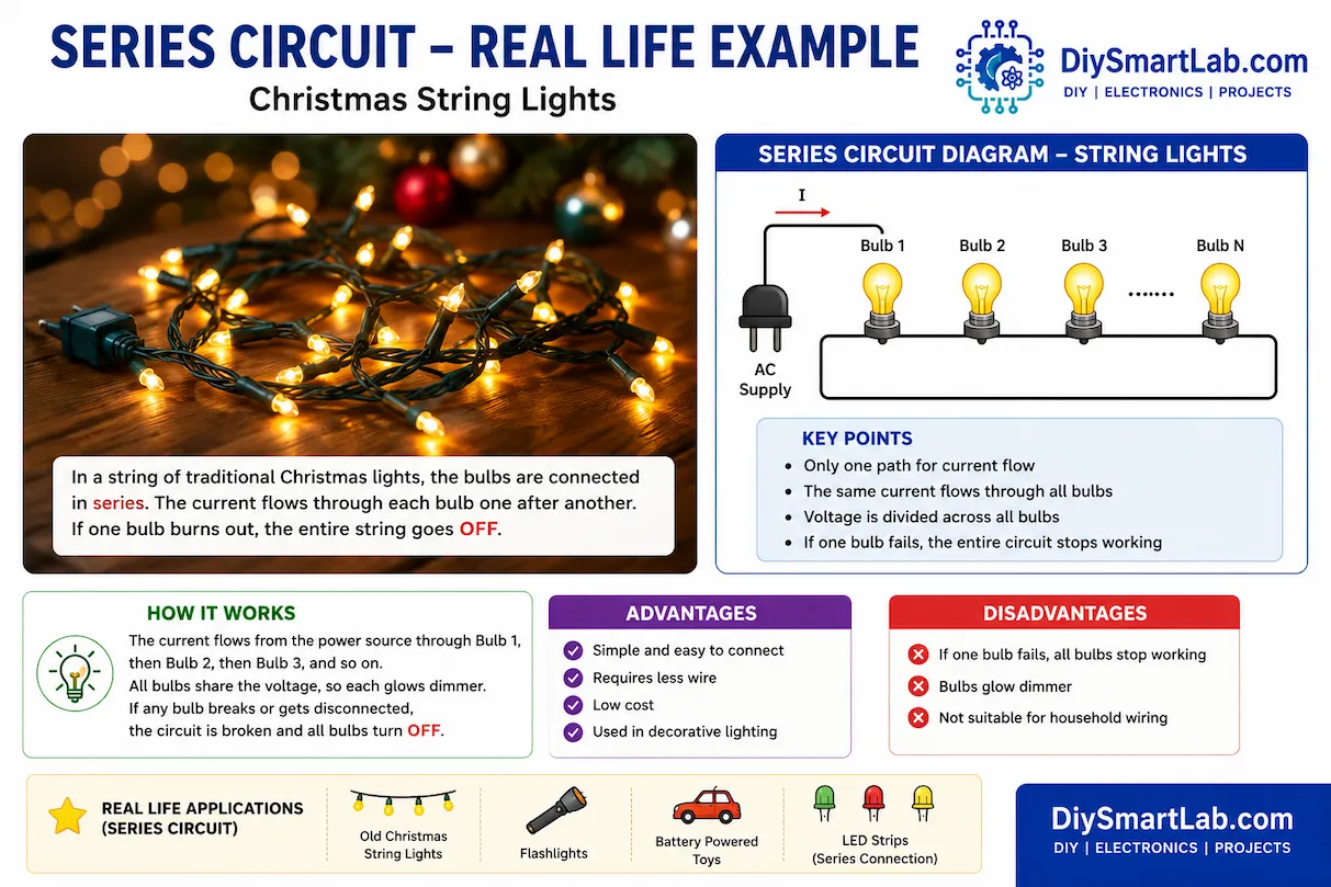
Real-Life Applications of Series Circuits
- Old decorative string lights
- Flashlights
- Simple LED circuits
- Battery-powered toys
Real-Life Applications of Parallel Circuits
- Home electrical wiring
- Power distribution systems
- Modern lighting systems
- Arduino and electronics projects

Series Circuit Formula
In a series circuit, the total resistance is calculated by adding all resistor values together.
Total Resistance:
Rtotal = R1 + R2 + R3
Parallel Circuit Formula
In a parallel circuit, the reciprocal of total resistance equals the sum of reciprocals of individual resistances.
1 / Rtotal = 1 / R1 + 1 / R2 + 1 / R3
Why Home Wiring Uses Parallel Circuits
Homes use parallel circuits because each appliance needs independent operation. If one bulb or appliance fails, other devices continue working normally. Parallel wiring also ensures all appliances receive the full supply voltage.
Beginner Experiment – Try It Yourself
You can easily test series and parallel circuits using:
- 2 LEDs
- 220Ω resistors
- Breadboard
- Battery
- Jumper wires
Build both circuits and observe brightness differences and behavior when disconnecting one LED.
Conclusion
Both series and parallel circuits are fundamental concepts in electronics. A series circuit provides a simple single-path design, while a parallel circuit offers independent operation and better reliability.
Understanding the difference between these circuit types helps beginners build better DIY electronics projects, Arduino systems, and home automation circuits. Mastering these basics is the first step toward becoming skilled in electronics.
Frequently Asked Questions (FAQs)
Which is better: series or parallel circuit?
Parallel circuits are generally better for practical applications because components work independently.
Why are house circuits connected in parallel?
Parallel circuits allow appliances to operate independently while receiving full voltage.
What happens if one bulb fails in a series circuit?
The entire circuit stops working because the current path breaks.
Do parallel circuits use more current?
Yes, parallel circuits can draw more total current because multiple branches operate simultaneously.
Are Arduino projects series or parallel?
Most Arduino projects use parallel connections so components can work independently.