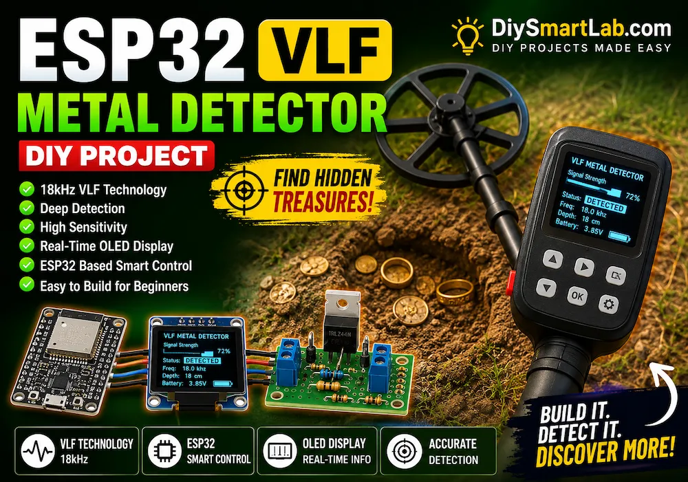
ESP32 VLF Metal Detector Using Si5351 – DIY Underground Metal Detection Project
ESP32 VLF Metal Detector Using Si5351 – DIY Underground Metal Detection Project
Building your own metal detector is one of the most exciting electronics projects for makers and hobbyists. It combines analog electronics, embedded programming, signal processing, and sensor technology into a single device. In this project, we will build an ESP32 VLF Metal Detector Using Si5351 that can detect underground metal objects and display real-time information on an OLED screen.
Unlike simple metal detector circuits that use a buzzer and a few transistors, this project uses an advanced architecture. It includes a stable 18kHz signal generator, a large 35cm search coil, amplifier and filter circuits, DSP filtering, and an ESP32 development board. As a result, the detector offers better stability, improved sensitivity, and more upgrade possibilities.
If you are interested in learning how professional metal detectors work, this project is an excellent starting point. Furthermore, it provides valuable experience with signal processing and embedded systems.

What Is a VLF Metal Detector?
VLF stands for Very Low Frequency. This technology is commonly used in modern metal detectors because it offers a good balance between sensitivity, stability, and metal discrimination capabilities.
A VLF metal detector uses two coils:
- Transmit Coil (TX) – Generates a magnetic field.
- Receive Coil (RX) – Detects changes caused by nearby metal objects.
When metal enters the magnetic field, it changes the electromagnetic characteristics around the coil. The receive coil senses these changes and sends a signal to the processing circuit.
The ESP32 then analyzes the signal and determines whether a metal target is present.
Why Use ESP32 for a Metal Detector?
The ESP32 is a powerful microcontroller that provides several advantages compared to traditional Arduino boards.
Because this project involves signal processing and filtering, the ESP32 is an excellent choice.
Benefits of ESP32
- Fast dual-core processor
- Built-in ADC inputs
- Large memory capacity
- Supports DSP filtering
- Easy OLED integration
- Low power consumption
- Future Bluetooth and WiFi support
- Advanced signal analysis capabilities
In addition, the ESP32 can be upgraded later with mobile applications, GPS logging, and advanced metal discrimination algorithms.
Why Use Si5351 Instead of AD9833?
Many DIY metal detector projects use the AD9833 signal generator. However, the AD9833 module has become difficult to find in some regions.
Fortunately, the Si5351 clock generator is an excellent alternative.
Advantages of Si5351
- Widely available
- Low cost
- Excellent frequency stability
- I2C communication with ESP32
- Programmable frequency generation
- Very low frequency drift
- Suitable for VLF applications
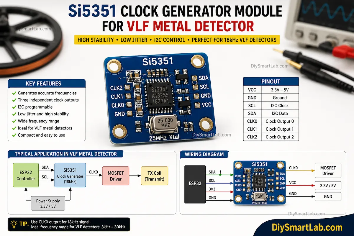
For this project, the Si5351 generates a stable 18kHz signal that drives the transmit coil.
Main Features of This Project
This ESP32 VLF Metal Detector includes several advanced features that are rarely found in beginner projects.
- ESP32-based smart controller
- Stable 18kHz VLF operation
- Si5351 frequency generator
- 35cm search coil
- MOSFET transmit driver
- Low-noise signal amplification
- 18kHz band-pass filtering
- DSP-based noise reduction
- Real-time OLED display
- Metal detection buzzer alerts
- Battery-powered operation
- Future metal discrimination support
Project Specifications
| Parameter | Value |
|---|---|
| Controller | ESP32 DevKit V1 |
| Frequency Generator | Si5351 |
| Operating Frequency | 18kHz |
| Display | 1.5 Inch OLED |
| Search Coil Diameter | 35cm |
| Detection Technology | VLF (Very Low Frequency) |
| Power Supply | 18650 Battery |
| Signal Processing | DSP Filtering |
How the ESP32 VLF Metal Detector Works
Understanding the working principle is important before building the circuit.
The detector begins by generating a stable 18kHz signal using the Si5351 module.
This signal drives the transmit coil through a MOSFET driver stage.
As a result, the transmit coil creates a magnetic field around the search area.
When a metal object enters this magnetic field, it disturbs the field and creates a detectable change.
The receive coil senses these changes and generates a very small electrical signal.
Next, the signal passes through several stages:
- Pre-Amplifier
- Band Pass Filter
- Gain Stage
- Precision Rectifier
- ESP32 ADC Input
Finally, the ESP32 applies DSP filtering and displays the results on the OLED screen.
Signal Flow Diagram
Si5351 Oscillator
        ↓
MOSFET Driver
        ↓
35cm TX Coil
        ↓
Magnetic Field
        ↓
35cm RX Coil
        ↓
Pre-Amplifier
        ↓
18kHz Band Pass Filter
        ↓
Gain Stage
        ↓
Precision Rectifier
        ↓
ESP32 ADC GPIO34
        ↓
DSP Processing
        ↓
OLED Display + Buzzer

Components Required
Before starting the build, gather all required components.
| Component | Quantity |
|---|---|
| ESP32 DevKit V1 | 1 |
| Si5351 Clock Generator Module | 1 |
| 1.5 Inch OLED Display | 1 |
| MCP6002 Op-Amp | 2 |
| IRLZ44N MOSFET | 1 |
| 18650 Battery | 1 |
| TP4056 Charger Module | 1 |
| Active Buzzer | 1 |
| Push Buttons | 2 |
| 35cm Search Coil Frame | 1 |
| Enamel Copper Wire | As Required |
| Resistors and Capacitors | Multiple |
Part 1 Ends Here.
In Part 2, we will cover:
- 35cm Search Coil Construction
- Complete Circuit Explanation
- ESP32 Pin Connections
- Power Supply Design
- Amplifier and Filter Section
- OLED Wiring
35cm Search Coil Construction
The search coil is the most important part of the entire metal detector. In fact, the overall performance of the detector depends heavily on the quality of the coil construction.
Therefore, spend extra time building and testing the coil carefully.
Transmit Coil (TX Coil)
The transmit coil generates the magnetic field used for metal detection.
| Parameter | Specification |
|---|---|
| Diameter | 35cm |
| Turns | 28 Turns |
| Wire Type | 0.5mm Enamel Copper Wire |
| Coil Shape | Round |
| Frame Material | PVC / Acrylic / Plastic |
Receive Coil (RX Coil)
The receive coil detects disturbances caused by metal objects.
| Parameter | Specification |
|---|---|
| Diameter | 33–35cm |
| Turns | 80–100 Turns |
| Wire Type | 0.35mm–0.45mm Enamel Copper Wire |
| Shielding | Recommended |
The RX coil should be positioned slightly offset from the TX coil. This helps reduce direct coupling and improves sensitivity.

Coil Shielding and Noise Reduction
Noise is one of the biggest problems in DIY metal detectors. Fortunately, proper shielding can significantly improve performance.
Use copper tape around the outside of the RX coil.
However, leave a small gap in the copper tape. Otherwise, a complete loop may create unwanted currents.
In addition, use shielded cable between the RX coil and amplifier circuit.
Noise Reduction Tips
- Use shielded cable for RX signals
- Keep analog traces short
- Separate analog and digital grounds
- Use battery power instead of wall adapters
- Turn off ESP32 WiFi and Bluetooth during detection
- Use a proper ground plane on the PCB
Complete Circuit Explanation
The ESP32 VLF Metal Detector is divided into several functional blocks.
Each block performs a specific task.
Block 1: Si5351 Oscillator
The Si5351 module generates a highly stable 18kHz square wave signal.
This signal becomes the reference frequency for the detector.
Because the frequency is digitally generated, drift is extremely low.
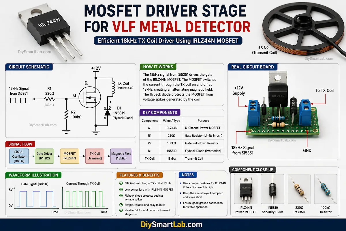
Block 2: MOSFET TX Driver
The output from the Si5351 is not powerful enough to drive the transmit coil directly.
Therefore, a MOSFET driver stage is required.
The MOSFET switches the TX coil current at 18kHz and creates the magnetic field.
| Component | Purpose |
|---|---|
| IRLZ44N | Main Driver MOSFET |
| 220Ω | Gate Resistor |
| 100kΩ | Gate Pull-down |
| 1N5819 | Protection Diode |
Block 3: Receive Coil
The receive coil captures changes in the magnetic field caused by nearby metal objects.
However, the signal is extremely weak.
Therefore, amplification is required before processing.
Block 4: Pre-Amplifier Stage
The MCP6002 operational amplifier boosts the receive signal.
This stage increases the signal amplitude without significantly increasing noise.
| Parameter | Value |
|---|---|
| Op-Amp | MCP6002 |
| Gain | Approx. 11x |
| Supply Voltage | 3.3V |
Block 5: 18kHz Band Pass Filter
After amplification, the signal passes through an active band-pass filter.
The purpose of this stage is to remove unwanted frequencies.
As a result, only signals around 18kHz are allowed to pass.
Benefits of the Band Pass Filter
- Reduces electrical noise
- Improves stability
- Increases sensitivity
- Improves signal-to-noise ratio
Block 6: Gain Stage
The filtered signal is amplified once again.
This additional gain makes weak targets easier to detect.
Furthermore, it improves the ESP32 ADC resolution.
Block 7: Precision Rectifier
The filtered signal is still an AC waveform.
Since the ESP32 ADC measures DC voltage levels, the signal must be converted.
The precision rectifier performs this conversion.
After rectification, the ESP32 can easily measure signal strength.

ESP32 Pin Connections
Proper wiring is important for stable operation.
| Function | ESP32 Pin |
|---|---|
| OLED SDA | GPIO21 |
| OLED SCL | GPIO22 |
| Si5351 SDA | GPIO21 |
| Si5351 SCL | GPIO22 |
| ADC Signal Input | GPIO34 |
| Buzzer Output | GPIO25 |
| Calibration Button | GPIO26 |
| Sensitivity Button | GPIO27 |
The OLED display and Si5351 module share the same I2C bus. Therefore, only two ESP32 pins are required for communication.
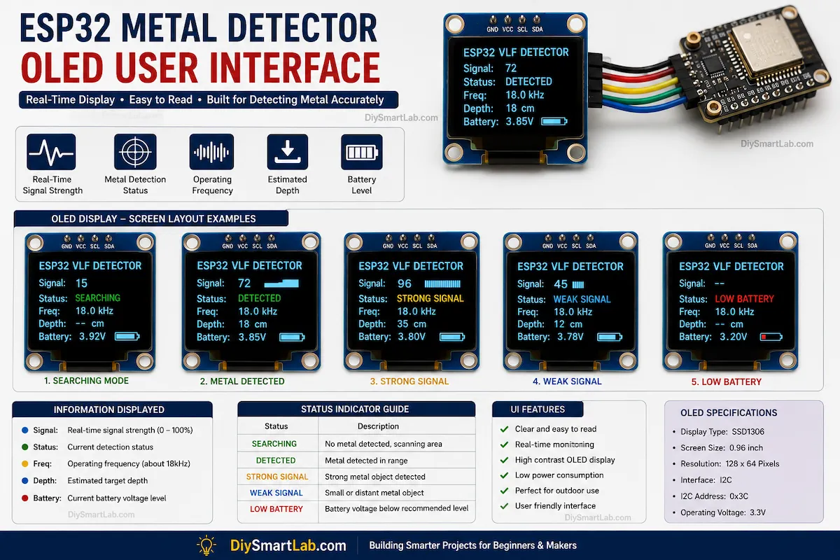
OLED Display Information
The OLED screen provides real-time detector status.
The following information can be displayed:
- Operating Frequency
- Signal Strength
- Noise Level
- Metal Detection Status
- Estimated Depth
- Battery Level

Power Supply Design
For portable operation, the detector uses an 18650 lithium-ion battery.
A TP4056 charging module is included for convenient charging.
| Component | Function |
|---|---|
| 18650 Battery | Main Power Source |
| TP4056 | Battery Charging |
| AMS1117 3.3V | Voltage Regulation |
| Power Switch | Main ON/OFF Control |
Battery operation is recommended because it reduces electrical noise and improves overall detector stability.
Part 2 Ends Here.
In Part 3, we will cover:
- Complete ESP32 Arduino Code
- Si5351 Programming
- DSP Filtering Techniques
- Metal Detection Logic
- OLED UI Programming
- Calibration Procedure
- Testing and Troubleshooting
Complete ESP32 Arduino Code
Now it is time to program the ESP32. This section covers the complete software architecture used in the ESP32 VLF Metal Detector.
The code performs several important functions:
- Reads the detector signal from GPIO34
- Applies DSP filtering
- Removes noise and false triggers
- Controls the buzzer
- Displays real-time data on the OLED screen
- Provides automatic calibration
- Calculates signal strength
Required Arduino Libraries
Install the following libraries before uploading the code:
- Adafruit GFX Library
- Adafruit SSD1306 Library
- Wire Library
- Etherkit Si5351 Library
Si5351 Frequency Generator Code
The Si5351 module generates a stable 18kHz reference frequency.
#include <Wire.h>
#include "si5351.h"

Si5351 si5351;

void setup()
{
Wire.begin();

si5351.init(SI5351_CRYSTAL_LOAD_8PF, 0);

si5351.set_freq(18000ULL * 100ULL,
SI5351_CLK0);

si5351.output_enable(SI5351_CLK0,1);
}

void loop()
{
}
The output from CLK0 is connected to the MOSFET driver stage.
Main ESP32 Metal Detector Program
#include <Wire.h>
#include <Adafruit_GFX.h>
#include <Adafruit_SSD1306.h>

#define SCREEN_WIDTH 128
#define SCREEN_HEIGHT 64

Adafruit_SSD1306 display(
SCREEN_WIDTH,
SCREEN_HEIGHT,
&Wire,
-1
);

#define ADC_PIN 34
#define BUZZER_PIN 25
#define CAL_BUTTON 26
#define SENS_BUTTON 27

float baseline=0;
float filtered=0;
float signalStrength=0;

float alpha=0.08;

void setup()
{
Serial.begin(115200);

pinMode(BUZZER_PIN,OUTPUT);

pinMode(CAL_BUTTON,INPUT_PULLUP);
pinMode(SENS_BUTTON,INPUT_PULLUP);

display.begin(
SSD1306_SWITCHCAPVCC,
0x3C
);

display.clearDisplay();
display.setTextColor(
SSD1306_WHITE
);

calibrate();
}

void loop()
{
float raw=
analogRead(ADC_PIN);

filtered=
(alpha*raw)+
((1-alpha)*filtered);

signalStrength=
abs(filtered-baseline);

if(signalStrength > 40)
{
digitalWrite(BUZZER_PIN,HIGH);
}
else
{
digitalWrite(BUZZER_PIN,LOW);
}

if(
digitalRead(CAL_BUTTON)
== LOW
)
{
calibrate();
}

updateDisplay();

delay(50);
}

void calibrate()
{
long sum=0;

for(int i=0;i<500;i++)
{
sum+=analogRead(ADC_PIN);
delay(2);
}

baseline=sum/500;
}

void updateDisplay()
{
display.clearDisplay();

display.setCursor(0,0);
display.print("ESP32 VLF");

display.setCursor(0,15);
display.print("Signal:");
display.print(signalStrength);

display.setCursor(0,30);
display.print("Base:");
display.print(baseline);

display.setCursor(0,45);

if(signalStrength > 40)
{
display.print("METAL");
}
else
{
display.print("SEARCHING");
}

display.display();
}
Understanding DSP Filtering
One of the biggest advantages of using ESP32 is digital signal processing.
Without filtering, the detector will generate many false alarms due to electrical noise.
Therefore, DSP filtering is essential.
What Is DSP Filtering?
DSP stands for Digital Signal Processing.
The ESP32 continuously analyzes the incoming signal and removes unwanted variations.
This improves stability and detection accuracy.
Filtering Techniques Used
| Filter | Purpose |
|---|---|
| Moving Average | Removes random spikes |
| Exponential Average | Smooths signal changes |
| Baseline Tracking | Compensates for drift |
| Threshold Detection | Reduces false triggers |
| Noise Rejection | Improves stability |
How Metal Detection Logic Works
The detector compares the current signal with the stored baseline value.
If the signal changes beyond a predefined threshold, a metal object is detected.
The larger the signal difference, the stronger the target response.
Detection Logic
Current Signal
      ↓
DSP Filtering
      ↓
Compare with Baseline
      ↓
Threshold Check
      ↓
Metal Detected?
      ↓
YES → OLED + Buzzer
NO  → Continue Scanning
OLED User Interface
The OLED display provides instant feedback to the user.
This makes the detector easier to operate in the field.
Displayed Information
- Signal Strength
- Baseline Value
- Metal Detection Status
- Frequency Information
- Battery Status (Future Upgrade)
- Sensitivity Level (Future Upgrade)
Calibration Procedure
Calibration is important because every coil and environment is different.
Perform calibration before each use.
Step 1
Move the detector away from metal objects.
Step 2
Power on the detector.
Step 3
Press the calibration button.
Step 4
Wait for the baseline value to stabilize.
Step 5
Begin scanning.
This process improves accuracy and reduces false alarms.
Testing the Detector
After calibration, test the detector using different metal objects.
Start with large objects because they are easier to detect.
Recommended Test Objects
- Iron Nail
- Copper Wire
- Aluminum Can
- Steel Washer
- Gold Ring
- Silver Coin
Record the signal strength for each object.
This helps you understand how the detector responds to different metals.
Expected Detection Depth
| Object Type | Typical Depth |
|---|---|
| Small Coin | 5–12cm |
| Ring | 8–18cm |
| Large Metal Object | 20–35cm |
| Large Buried Target | 35–40cm |
Actual results depend on coil tuning, soil conditions, and environmental noise.
Troubleshooting Guide
| Problem | Possible Cause | Solution |
|---|---|---|
| No Detection | Incorrect wiring | Check all connections |
| Constant Beeping | Improper calibration | Recalibrate detector |
| Weak Detection | Low amplifier gain | Adjust gain stage |
| Noisy Signal | Poor shielding | Use shielded cable |
| OLED Not Working | Wrong I2C address | Verify OLED address |
Future Upgrades
After the basic detector is working, several advanced features can be added.
- Ground Balance System
- Automatic Gain Control
- Phase Detection Circuit
- Ferrous/Non-Ferrous Classification
- Bluetooth Connectivity
- Mobile Application Support
- GPS Logging
- Rechargeable Battery Monitor
- Graphical Signal Display
These upgrades can significantly improve performance and user experience.
Part 3 Ends Here.
In Part 4, we will cover:
- Applications
- Advantages
- Disadvantages
- FAQs
- Conclusion
- SEO Meta Data
- FAQ Schema
- Article Schema Markup
- Internal Linking Box
Applications of ESP32 VLF Metal Detector
The ESP32 VLF Metal Detector can be used for many educational and practical purposes. Although it is a DIY project, it demonstrates many technologies used in professional metal detectors.
Common Applications
- Electronics learning projects
- Metal detection experiments
- Underground object detection
- STEM education projects
- Signal processing research
- Embedded systems development
- Coil design experiments
- Sensor technology learning
Furthermore, this project provides a strong foundation for developing more advanced detection systems in the future.

Advantages of ESP32 VLF Metal Detector
This project offers several benefits compared to traditional DIY detector circuits.
- Uses modern ESP32 microcontroller
- Stable Si5351 frequency generation
- DSP-based noise reduction
- OLED real-time monitoring
- Upgradeable architecture
- Low-cost development platform
- Battery-powered operation
- Educational and practical design
- Supports future metal classification upgrades
- Excellent learning experience
Disadvantages of ESP32 VLF Metal Detector
Although this detector is powerful, it also has some limitations.
- Requires careful calibration
- Sensitive to environmental noise
- Coil tuning can be challenging
- Detection depth depends on soil conditions
- Cannot guarantee gold-only identification
- Requires analog circuit knowledge
- Needs proper shielding for best results
Frequently Asked Questions (FAQs)
1. Can this detector find gold?
Yes. The detector can detect gold objects because gold affects the electromagnetic field generated by the search coil. However, it cannot guarantee 100% gold identification without advanced phase analysis.
2. Why is Si5351 used instead of AD9833?
The Si5351 is easier to find, more affordable, and provides excellent frequency stability. It is also easy to interface with ESP32 through I2C communication.
3. What frequency does this detector use?
This project uses an operating frequency of approximately 18kHz, which is suitable for VLF metal detection.
4. Can I increase the detection depth?
Yes. Larger coils, improved filtering, better shielding, and proper ground balancing can increase detection depth.
5. Is ESP32 better than Arduino Uno for this project?
Yes. ESP32 offers significantly higher processing power, larger memory, faster ADC operation, and support for advanced DSP algorithms.
6. Can this project distinguish between different metals?
The basic version mainly detects metal presence. Future upgrades with phase detection can improve ferrous and non-ferrous metal discrimination.
7. What power source should I use?
An 18650 lithium-ion battery is recommended because it provides stable power and reduces electrical noise.
8. Is this project suitable for beginners?
Yes. Beginners can build the project step by step. However, some experience with soldering and electronics is helpful.
Project Improvements and Future Enhancements
Once the detector is working successfully, you can add several advanced features.
Recommended Upgrades
- Ground Balance System
- Automatic Sensitivity Control
- Bluetooth Communication
- Mobile Application Integration
- Graphical Signal Display
- Rechargeable Battery Monitoring
- GPS Location Logging
- Advanced Phase Detection Circuit
- Metal Classification Algorithms
- Data Logging to SD Card
These upgrades can transform the project into a highly advanced experimental metal detector.
Safety Notes
Always follow basic safety precautions while building and testing electronics projects.
- Double-check all wiring before powering the circuit.
- Use proper battery protection.
- Avoid short circuits.
- Do not expose the electronics to water.
- Keep the detector away from strong electromagnetic interference sources.
- Use insulated tools during assembly.
Conclusion
The ESP32 VLF Metal Detector Using Si5351 is an exciting and educational DIY electronics project. It combines analog electronics, digital signal processing, embedded programming, and sensor technology into a single system.
By using a stable 18kHz VLF signal, a large 35cm search coil, amplifier circuits, DSP filtering, and an OLED display, this project provides significantly better performance than simple buzzer-based metal detectors.
In addition, the ESP32 offers plenty of room for future upgrades such as Bluetooth communication, mobile applications, phase detection, and advanced metal classification.
If you want to learn how modern metal detection systems work, this project is an excellent hands-on learning experience. At DiySmartLab.com, we believe practical projects like this are the best way to improve your electronics and embedded systems skills.

