Simple LED Chaser Circuit Without Arduino | Easy 4017 IC Project
Simple LED Chaser Circuit Without Arduino
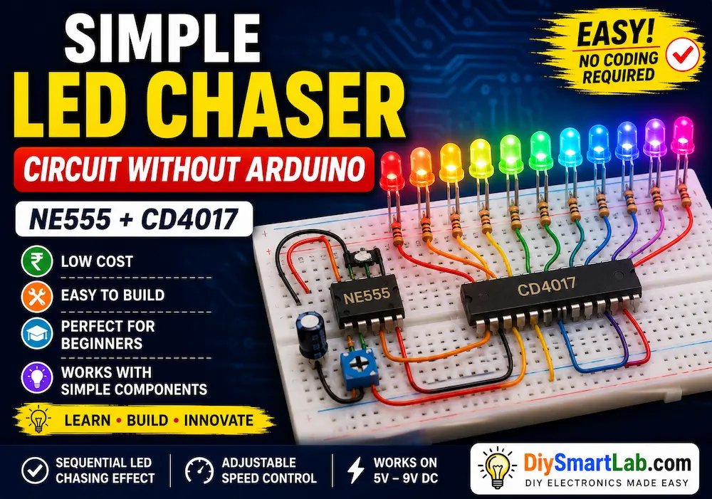
A Simple LED Chaser Circuit Without Arduino is one of the best beginner electronics projects for learning how LEDs blink in sequence automatically. This circuit creates a running light effect where LEDs turn ON and OFF one after another, creating an attractive chasing pattern. The project is simple, low-cost, and perfect for students, DIY hobbyists, and electronics beginners.
In this tutorial by DiySmartLab.com, you will learn how the LED chaser circuit works, required components, circuit connections, working principle, applications, advantages, and troubleshooting tips.
What is an LED Chaser Circuit?
An LED chaser circuit is an electronic circuit where multiple LEDs glow in a sequential pattern. The LEDs switch ON one after another repeatedly, creating a moving light effect. This project is commonly used in decorative lights, advertising displays, and beginner electronics learning.
Unlike Arduino-based projects, this circuit works using the famous NE555 Timer IC and CD4017 Decade Counter IC, making it a great project to understand basic digital electronics.
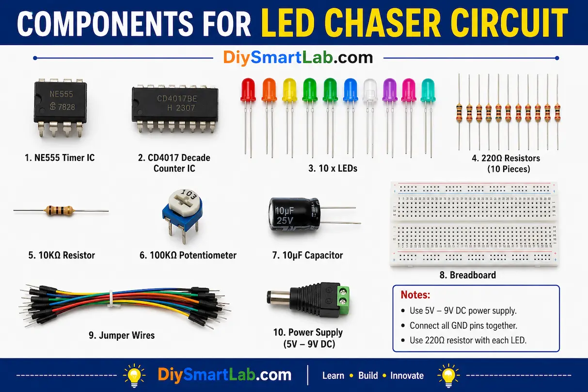
Components Required
- NE555 Timer IC
- CD4017 Decade Counter IC
- 10 LEDs
- 220Ω Resistors (10 pieces)
- 10KΩ Resistor
- 100KΩ Potentiometer
- 10µF Capacitor
- Breadboard
- Jumper Wires
- 5V to 9V Power Supply
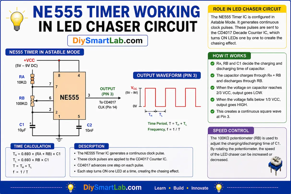
NE555 Timer IC Working
The NE555 Timer IC works as an astable multivibrator in this project. It continuously generates clock pulses automatically. These pulses are sent to the CD4017 counter IC.
The blinking speed depends on the resistor and capacitor values connected to the NE555 timer circuit. By rotating the potentiometer, you can increase or decrease the LED chasing speed.
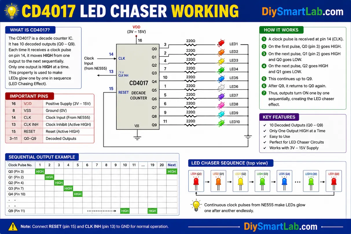
CD4017 Decade Counter IC Working
The CD4017 is a decade counter IC that activates its output pins sequentially. Each time it receives a pulse from the NE555 timer, the output shifts to the next LED.
This sequential switching creates the LED chasing effect. Only one output remains HIGH at a time, which helps create a clean running light pattern.
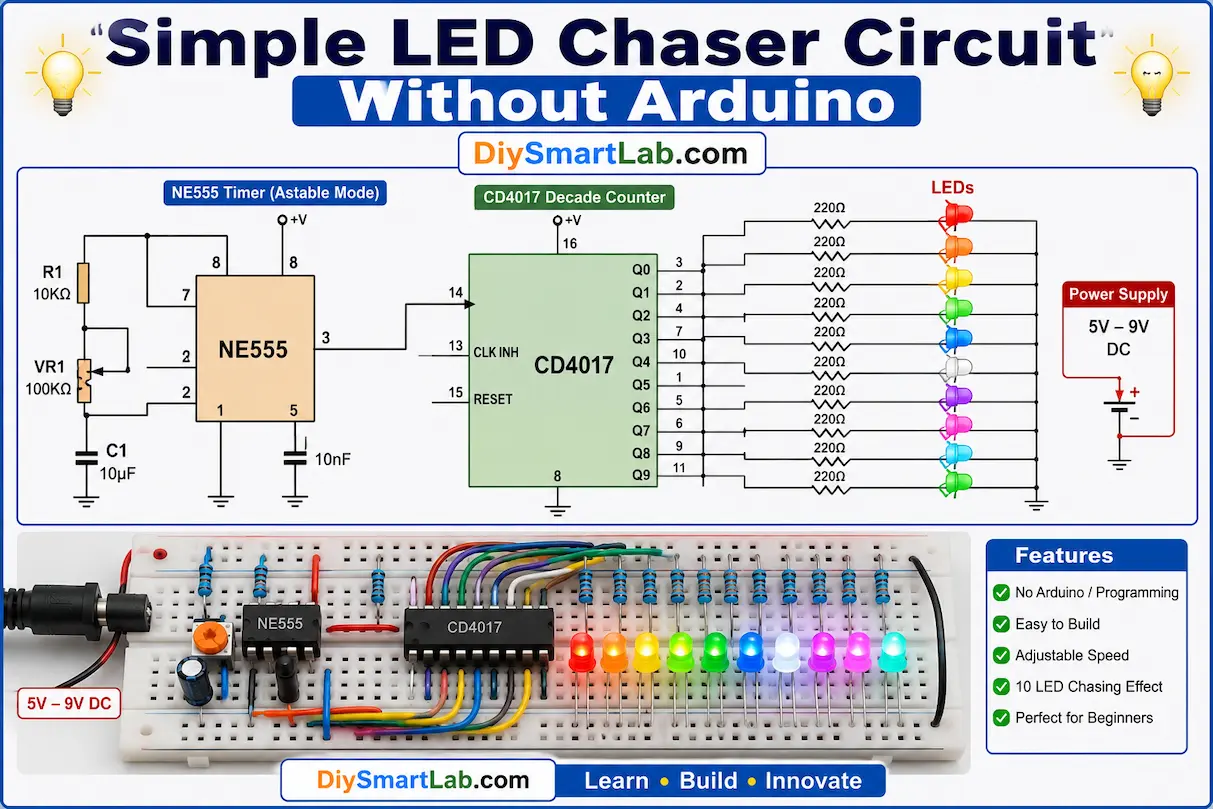
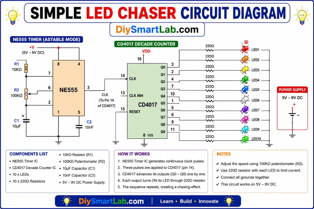
Simple LED Chaser Circuit Diagram
In this circuit:
- NE555 Timer generates clock pulses
- CD4017 receives pulses and activates outputs one by one
- Each LED connects to one output pin through a 220Ω resistor
- The potentiometer controls LED speed
Breadboard Connections
- Connect NE555 Timer in astable mode
- Connect pin 3 of NE555 to pin 14 of CD4017
- Connect LEDs to output pins Q0 to Q9
- Use resistors with every LED
- Connect all grounds together
- Provide 5V to 9V power supply
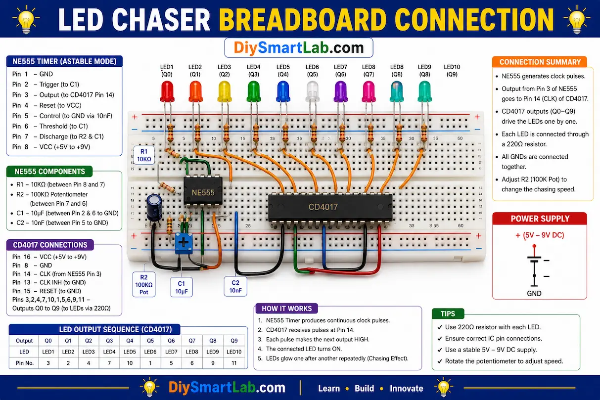
How the LED Chaser Circuit Works
When power is supplied:
- NE555 Timer starts generating clock pulses
- CD4017 receives these pulses
- Each pulse activates the next output pin
- The connected LED turns ON
- LEDs glow one after another repeatedly
- The sequence continues automatically
Applications of LED Chaser Circuit
- Decorative lighting projects
- LED advertising displays
- DIY electronic learning projects
- Sequential light systems
- Festival lighting effects
- School and college mini projects
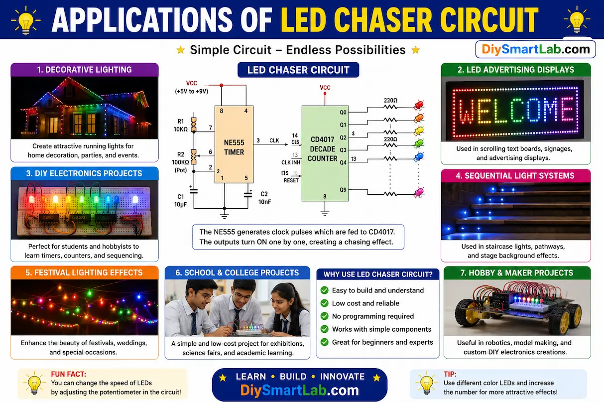
Advantages of This Circuit
- No programming required
- Easy to build for beginners
- Low-cost electronic project
- Adjustable LED speed
- Works without Arduino or microcontroller
- Excellent for learning IC basics
Troubleshooting Tips
- Check LED polarity carefully
- Verify NE555 and CD4017 pin connections
- Ensure power supply voltage is correct
- Use proper resistor values
- Check loose breadboard wires
- Replace faulty LEDs if needed
Conclusion
The Simple LED Chaser Circuit Without Arduino is a fun and educational electronics project for beginners. It helps you understand timer circuits, digital counters, LED sequencing, and breadboard wiring without needing any coding knowledge.
This project is perfect for school projects, DIY electronics practice, and decorative lighting experiments. Try modifying the circuit with different LEDs, speed settings, or additional effects to create your own custom light patterns.
Frequently Asked Questions (FAQs)
Can I make an LED chaser circuit without Arduino?
Yes, you can build an LED chaser circuit using NE555 Timer IC and CD4017 counter IC without using Arduino.
What is the purpose of CD4017 IC?
The CD4017 IC activates output pins sequentially to create the LED chasing effect.
How can I control LED chasing speed?
You can adjust the speed using a potentiometer connected to the NE555 timer circuit.
What voltage is required for this project?
The circuit normally works using a 5V to 9V DC power supply.
Is this project suitable for beginners?
Yes, this is one of the easiest and most popular beginner electronics projects.