Smart Street Light Using LDR and Arduino
Want to build a smart street light using LDR and Arduino that automatically turns ON at night and OFF during the day? In this step-by-step tutorial, you’ll learn exactly how to wire, program, and test an automatic street light system using an LDR (Light Dependent Resistor) and an Arduino Uno — perfect for beginners and electronics enthusiasts alike.
This project is a great introduction to sensor-based automation and forms the foundation for more advanced smart home and smart city projects. By the end, you’ll have a fully working prototype that mimics real-world automatic street lighting.
Table of Contents
- What is an LDR (Light Dependent Resistor)?
- How Does the Smart Street Light Work?
- Components Required
- Circuit Diagram
- Wiring Connections
- Arduino Code
- Code Explanation
- Working of the Project
- Applications
- Conclusion
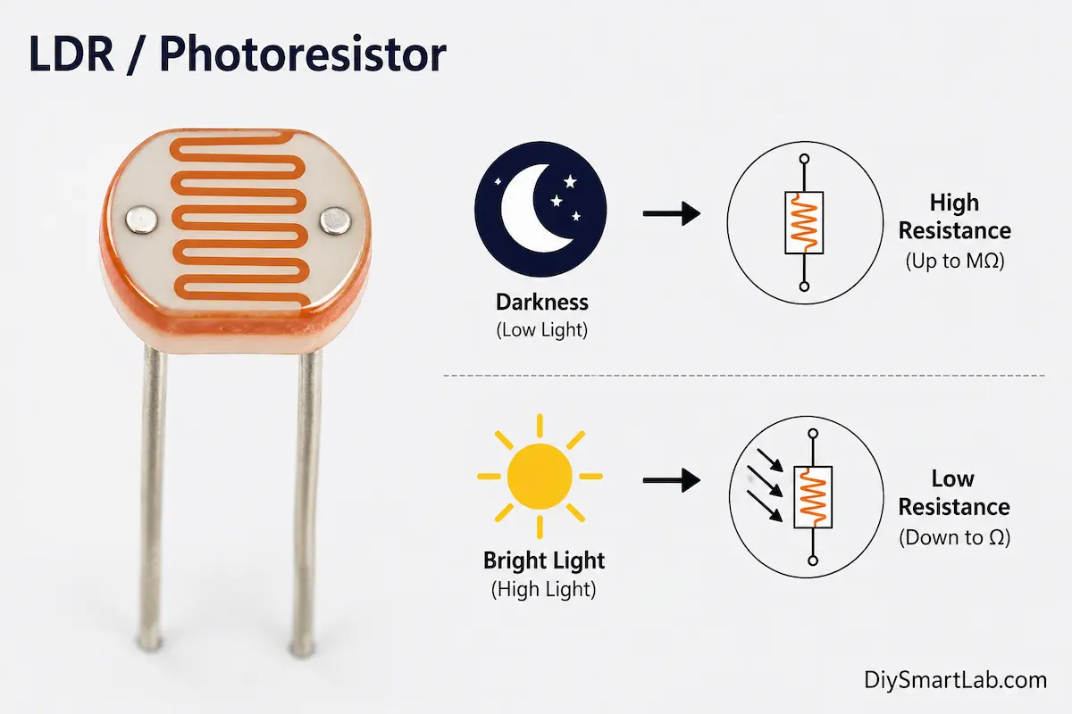
What is an LDR (Light Dependent Resistor)?
An LDR (Light Dependent Resistor), also called a photoresistor or photocell, is a variable resistor whose resistance changes based on the intensity of light falling on it.
- In bright light → resistance is very LOW (a few hundred ohms)
- In darkness → resistance is very HIGH (several mega-ohms)
This property makes the LDR ideal for light-sensing applications like automatic street lights, day/night detection, and light-controlled switches.
How Does the Smart Street Light Work?
The working principle of this automatic street light project is simple and elegant:
- The LDR sensor continuously monitors the surrounding light level.
- The Arduino reads the analog voltage from the LDR via a voltage divider circuit.
- When it gets dark (voltage drops below a set threshold), Arduino turns the LED / streetlight ON.
- When it gets bright (voltage rises above the threshold), Arduino turns the LED / streetlight OFF.
This is exactly how real automatic street lights work in smart cities — saving energy by operating only when needed.
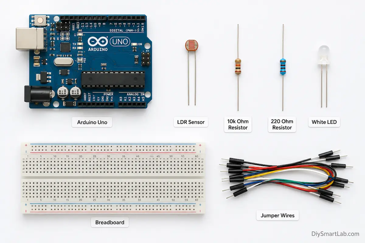
Components Required
Here’s a complete list of all the components you’ll need to build this smart street light using Arduino and LDR:
| # | Component | Quantity |
|---|---|---|
| 1 | Arduino Uno (or Nano) | 1 |
| 2 | LDR (Light Dependent Resistor) | 1 |
| 3 | 10kΩ Resistor (for voltage divider) | 1 |
| 4 | 220Ω Resistor (for LED) | 1 |
| 5 | LED (White or Yellow — simulates streetlight) | 1 |
| 6 | Breadboard | 1 |
| 7 | Jumper Wires | As needed |
| 8 | USB Cable (for Arduino) | 1 |
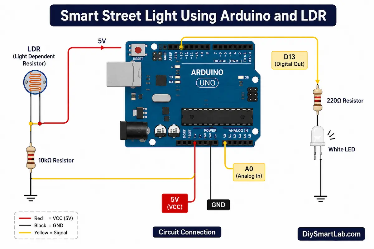
Circuit Diagram
Below is the circuit diagram for the smart automatic street light project. Study it carefully before proceeding to the wiring step.
Wiring Connections
Follow these connections carefully to assemble the circuit on your breadboard:
LDR Voltage Divider Circuit (to Arduino A0)
| From | To |
|---|---|
| LDR Pin 1 | Arduino 5V |
| LDR Pin 2 | Arduino A0 (Analog Input) + 10kΩ Resistor |
| 10kΩ Resistor other end | GND (Ground) |
LED Connection (to Arduino Pin 13)
| From | To |
|---|---|
| LED Anode (+) | Arduino Pin 13 (via 220Ω resistor) |
| LED Cathode (–) | GND (Ground) |
The 10kΩ resistor and LDR form a voltage divider. As light decreases, LDR resistance increases, causing the voltage at A0 to drop — which the Arduino reads to decide whether to turn the LED on or off.
Arduino Code for Smart Street Light
Copy and upload the following Arduino sketch to your board using the Arduino IDE:
// ============================================
// Smart Street Light using LDR and Arduino
// DIY Smart Lab - diysmartlab.com
// ============================================

const int ldrPin = A0;     // LDR connected to Analog Pin A0
const int ledPin = 13;     // LED connected to Digital Pin 13
int threshold = 500;       // Adjust this value based on your environment

void setup() {
  pinMode(ledPin, OUTPUT);   // Set LED pin as OUTPUT
  Serial.begin(9600);        // Start Serial Monitor for debugging
  Serial.println("Smart Street Light - DIY Smart Lab");
}

void loop() {
  int ldrValue = analogRead(ldrPin);  // Read LDR analog value (0-1023)

  Serial.print("LDR Value: ");
  Serial.println(ldrValue);

  if (ldrValue < threshold) {
    // It's DARK — Turn ON the street light
    digitalWrite(ledPin, HIGH);
    Serial.println("Status: DARK → Light ON");
  } else {
    // It's BRIGHT — Turn OFF the street light
    digitalWrite(ledPin, LOW);
    Serial.println("Status: BRIGHT → Light OFF");
  }

  delay(500);  // Wait 500ms before next reading
}
Code Explanation
Let’s break down the Arduino code step by step so you understand exactly what’s happening:
1. Pin & Threshold Definitions
const int ldrPin = A0;
const int ledPin = 13;
int threshold = 500;
We define the LDR connected to Analog Pin A0 and the LED to Digital Pin 13. The threshold value of 500 (out of 1023) is the cutoff point between day and night. You can adjust this value based on your lighting conditions.
2. Setup Function
void setup() {
  pinMode(ledPin, OUTPUT);
  Serial.begin(9600);
}
The setup() function initializes the LED pin as an OUTPUT and starts the Serial Monitor at 9600 baud so we can observe the LDR readings in real-time.
3. Loop Function (Main Logic)
int ldrValue = analogRead(ldrPin);

if (ldrValue < threshold) {
  digitalWrite(ledPin, HIGH);   // DARK → Light ON
} else {
  digitalWrite(ledPin, LOW);    // BRIGHT → Light OFF
}
The analogRead() function reads a value between 0 and 1023 from the LDR. When this value is below the threshold (meaning it’s dark), the LED turns ON. When it’s above the threshold (meaning it’s bright), the LED turns OFF.
threshold to a value between the two readings for the most accurate switching.Working of the Smart Street Light Project
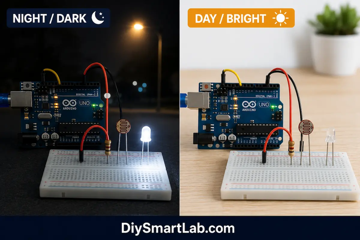
Here’s how the complete system behaves in real-time:
- Power ON: Arduino powers up and starts reading the LDR every 500ms.
- Daytime (Bright Light): LDR resistance is low → high voltage at A0 → analogRead value is HIGH (e.g., 800–1023) → LED stays OFF.
- Evening / Darkness: LDR resistance increases → voltage at A0 drops → analogRead value goes LOW (e.g., below 500) → LED turns ON.
- Dawn: Light increases again → LDR reads high → LED automatically turns OFF.
This seamless automatic switching is what makes this an intelligent, energy-efficient street light.
Upgrading with a Relay Module (For Real Bulbs)
Want to control an actual high-power street light or bulb instead of a small LED? Simply add a 5V relay module between Arduino and the light:
- Connect relay IN to Arduino Pin 13
- Connect your AC bulb or LED strip through the relay’s NO (Normally Open) and COM terminals
- The same code works — no changes needed!
⚠️ Safety Warning: Be extremely careful when working with mains AC voltage (220V/110V). Use proper insulation and ensure the relay is rated for the load. If you’re new to electronics, stick with the LED version for now.
Applications of Smart Street Light Using LDR
This simple yet powerful project has many real-world use cases:
- 🌃 Automatic Street Lighting — Turns ON at dusk, OFF at dawn, saving electricity
- 🏠 Smart Home Garden Lights — Automate outdoor garden or pathway lighting
- 🏭 Industrial Lighting Automation — Automate factory or warehouse lights based on natural light
- 🌱 Greenhouse Lighting Control — Supplement natural light for plant growth
- 🏫 School Science Projects — Demonstrates sensor-based automation concepts
- 🌆 Smart City Infrastructure — Building block for larger IoT-based city lighting systems
Troubleshooting Common Problems
Running into issues? Here are the most common problems and their fixes:
| Problem | Possible Cause | Fix |
|---|---|---|
| LED always ON | Threshold too high or LDR not connected properly | Lower the threshold value or check LDR wiring |
| LED never turns ON | Threshold too low | Increase the threshold value |
| Erratic behavior / flickering | Threshold set near ambient light level | Add a small hysteresis band (±50) around threshold |
| No Serial output | Wrong baud rate in Serial Monitor | Set Serial Monitor to 9600 baud |
| LED dim or not bright | Missing or wrong LED resistor | Use correct 220Ω resistor in series |
Frequently Asked Questions (FAQs)
Q1: What is the working principle of the smart street light using LDR?
The LDR’s resistance changes with light intensity. When connected in a voltage divider with a 10kΩ resistor, the Arduino reads the changing voltage on its analog pin. The code compares this reading to a threshold and switches the light ON or OFF accordingly.
Q2: Can I use this project without Arduino?
Yes! A simpler version can be made using just an LDR, transistor (BC547), and a relay — no microcontroller needed. However, the Arduino version gives you more control, customization, and the ability to add features like timers or WiFi connectivity.
Q3: How do I set the correct threshold value?
Open the Arduino Serial Monitor and observe the LDR values in full light and in darkness. Set your threshold roughly in the middle of those two values. For example, if bright reads 900 and dark reads 100, set the threshold to around 500.
Q4: Can I control multiple lights with this circuit?
Absolutely! You can connect multiple LEDs or relay-controlled lights to different digital output pins of the Arduino and control them all using the same LDR reading or individual sensor readings.
Q5: What is the cost to build this project?
This is one of the most affordable Arduino projects. The total cost is typically under ₹150–₹200 (around $2–$3 USD) if you already have an Arduino. The LDR costs just a few rupees, making it extremely budget-friendly for students and hobbyists.
Conclusion
Congratulations! 🎉 You’ve successfully built a Smart Street Light using LDR and Arduino. This project demonstrates the power of sensor-based automation — a core concept in IoT and smart city development.
With just a few inexpensive components, you’ve created a system that:
- ✅ Automatically turns ON at night
- ✅ Automatically turns OFF during daylight
- ✅ Saves energy without manual intervention
- ✅ Can be scaled up for real-world use with a relay module
This project is a fantastic stepping stone for more advanced builds like motion-activated lights, WiFi-controlled smart lighting with ESP8266/ESP32, or even a full smart home automation system.
If you found this tutorial helpful, share it with your friends and leave a comment below with your experience or questions. Happy Building! 🛠️

One thought on “Smart Street Light Using LDR and Arduino”