Automatic Night Lamp Using LDR | Simple DIY Electronics Project
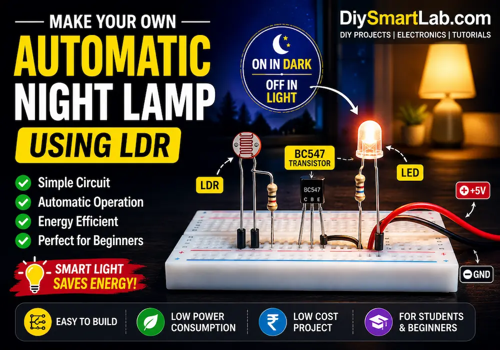
Automatic Night Lamp Using LDR – Simple DIY Circuit for Beginners
An Automatic Night Lamp Using LDR is one of the easiest and most useful DIY electronics projects for beginners. This smart circuit automatically turns ON the light during darkness and turns it OFF during daylight. It works using an LDR (Light Dependent Resistor), which changes its resistance according to light intensity.
In this tutorial by DiySmartLab.com, you will learn the working principle, components required, circuit diagram, connections, and applications of an automatic night lamp project.

What is an Automatic Night Lamp?
An automatic night lamp is a smart lighting system that automatically switches ON when the surrounding environment becomes dark and switches OFF when light is available. The main sensing component used in this project is an LDR sensor.
This type of project is commonly used in:
- Street lights
- Garden lighting systems
- Bedroom night lamps
- Outdoor automatic lighting
- Smart home automation projects
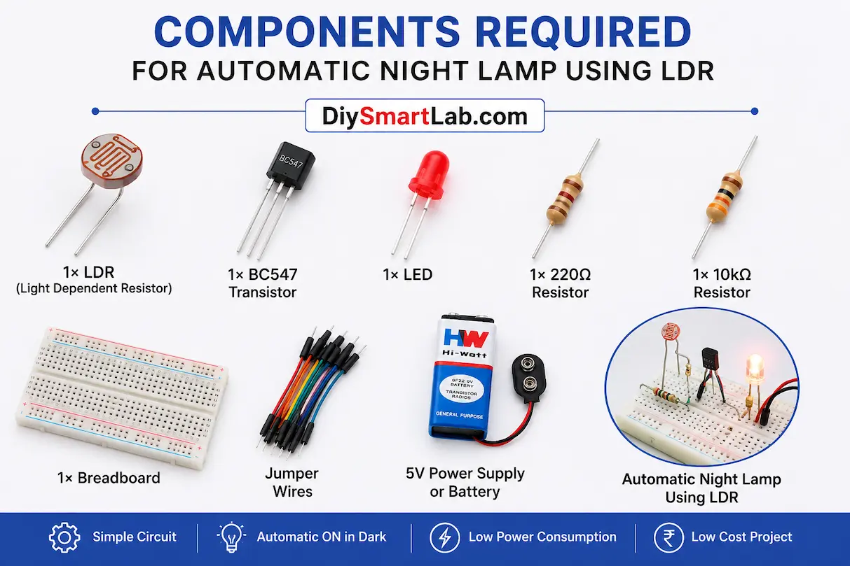
Components Required
- 1× LDR (Light Dependent Resistor)
- 1× BC547 Transistor
- 1× LED
- 1× 10kΩ Resistor
- 1× 220Ω Resistor
- 1× Breadboard
- Jumper wires
- 5V Power Supply or Battery
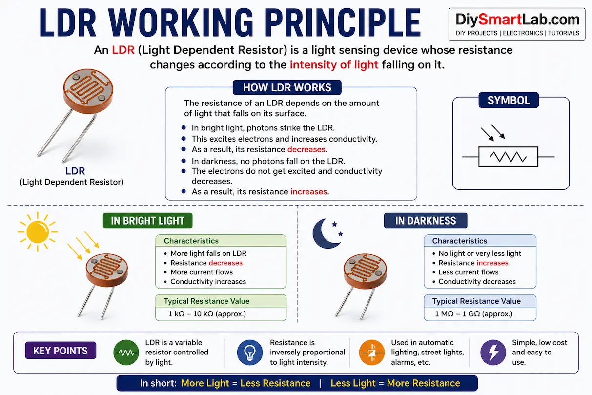
What is an LDR?
An LDR (Light Dependent Resistor) is a special resistor whose resistance changes according to the intensity of light. In bright light, the resistance becomes very low, while in darkness, the resistance becomes very high.
This property makes the LDR perfect for automatic lighting projects.
Automatic Night Lamp Circuit Diagram
The circuit uses an LDR and transistor combination to control the LED automatically.
- The LDR senses the surrounding light level.
- In daylight, the transistor remains OFF and the LED stays OFF.
- In darkness, the transistor turns ON and powers the LED.
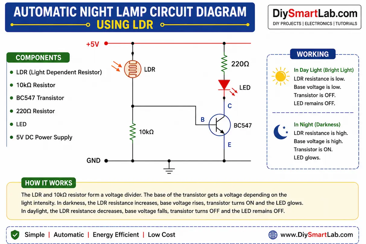
How the Automatic Night Lamp Works
The working principle of this project is very simple:
- During daylight, light falls on the LDR.
- The resistance of the LDR decreases.
- The transistor does not receive enough bias current.
- The LED remains OFF.
- When darkness occurs, the resistance of the LDR increases.
- The transistor gets base current and turns ON.
- The LED automatically glows.
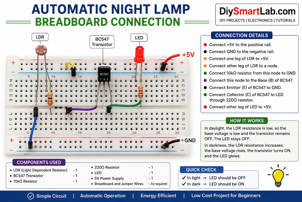
Connection Steps
- Connect the LDR to the breadboard.
- Connect one side of the LDR to VCC.
- Connect the other side to the transistor base through a resistor.
- Connect the transistor emitter to GND.
- Connect the LED with a 220Ω resistor to the transistor collector.
- Power the circuit using a 5V supply.
Advantages of Automatic Night Lamp Using LDR
- Energy efficient lighting system
- Fully automatic operation
- Low-cost project for beginners
- Easy to build at home
- Useful for smart home projects
- Low power consumption
Applications of LDR Night Lamp
- Automatic street lighting
- Garden lamps
- Home night lamps
- Outdoor lighting systems
- Solar lighting systems
- Smart city projects
Tips for Better Performance
- Use a good-quality LDR sensor.
- Keep the LDR exposed to ambient light.
- Use proper resistor values for stable switching.
- Avoid direct LED light falling on the LDR.
- Use a transistor or relay for higher loads.
Conclusion
The Automatic Night Lamp Using LDR is a simple yet practical electronics project for beginners. It helps you understand the working of sensors, transistors, and automatic control systems. This project is widely used in smart lighting and home automation systems.
If you are learning electronics or Arduino projects, this DIY project from DiySmartLab.com is a perfect starting point.
Frequently Asked Questions (FAQs)
What is the purpose of an LDR in an automatic night lamp?
The LDR senses light intensity and automatically controls the lamp according to surrounding light conditions.
Can I use a relay instead of a transistor?
Yes, a relay can be used for controlling AC bulbs or high-power devices.
Does this project require Arduino?
No, this is a simple electronics project without Arduino.
What voltage is required for this project?
You can power the circuit using a 5V DC supply or battery.
Can this circuit control an AC bulb?
Yes, by adding a relay module, the circuit can control AC home lighting safely.