Clap Switch Circuit for Beginners – Simple DIY Sound Activated Switch Project
Clap Switch Circuit for Beginners – Simple DIY Sound Activated Switch Project
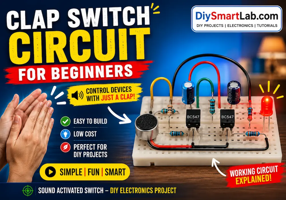
A Clap Switch Circuit is one of the most popular beginner-friendly DIY electronics projects. This circuit can turn ON or OFF an electrical device when it detects a clap sound. It is simple, fun to build, and a great way to learn about sound sensors, transistors, and switching circuits.
In this guide from DiySmartLab.com, you will learn how a clap switch works, required components, circuit connections, working principle, applications, advantages, and safety tips.
What is a Clap Switch Circuit?
A clap switch is an electronic circuit that controls a device using sound, usually a hand clap. When the microphone detects the clap sound, the circuit activates a relay or LED.
Clap switch circuits are commonly used in:
- Home automation projects
- Sound-controlled lights
- DIY smart switch systems
- School and college electronics projects
- Arduino and sensor experiments
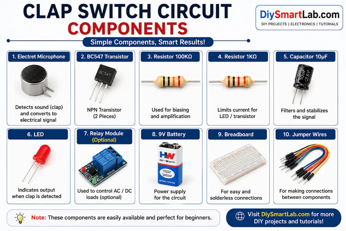
Components Required
- Electret Microphone
- BC547 Transistor – 2 pieces
- 100K Resistor
- 1K Resistor
- 10uF Capacitor
- LED
- Relay Module (optional)
- 9V Battery
- Breadboard
- Jumper Wires
How Does a Clap Switch Work?
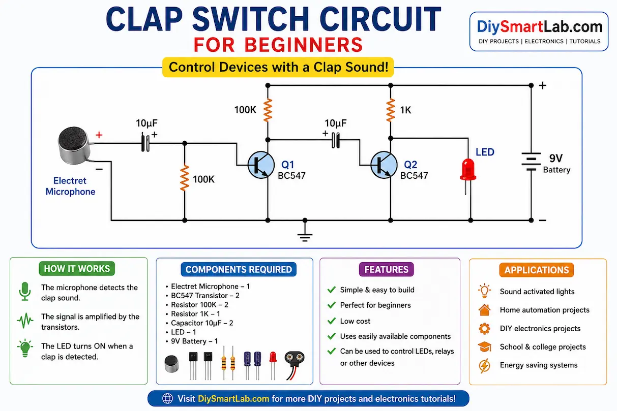
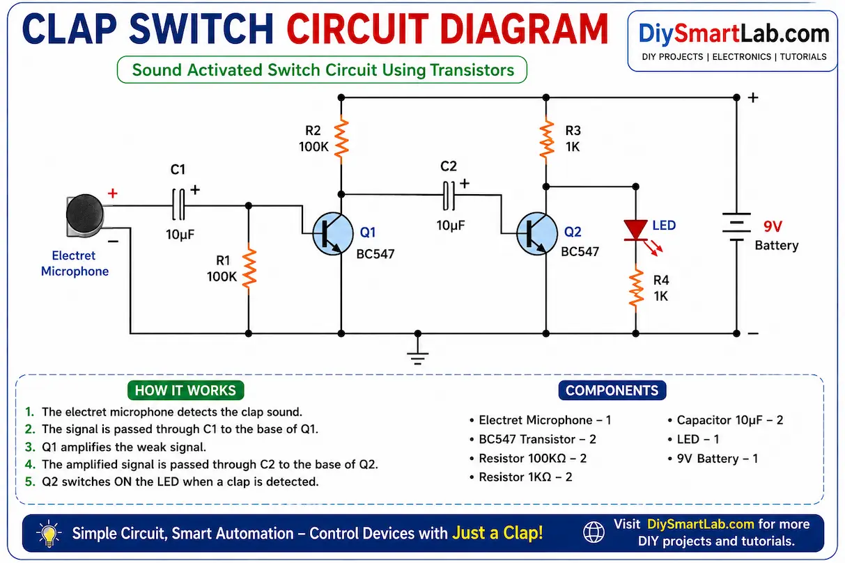
The microphone detects sound vibrations from a clap and converts them into small electrical signals. These weak signals are amplified using transistors. Once the signal becomes strong enough, it activates the LED or relay connected to the circuit.
Here is the simple working process:
- The microphone detects clap sound.
- The transistor amplifies the signal.
- The capacitor stabilizes the pulse.
- The output transistor switches ON the LED or relay.
- The connected device turns ON or OFF.
Simple Clap Switch Circuit Diagram
The basic clap switch circuit contains a microphone, transistor amplifier stage, capacitor filtering section, and output switching stage.
Step-by-Step Circuit Connections
- Place both BC547 transistors on the breadboard.
- Connect the microphone output to the transistor base through a resistor.
- Connect the capacitor between transistor stages.
- Attach the LED with a 1K resistor to the output transistor.
- Connect the battery supply.
- Clap near the microphone and observe the LED response.
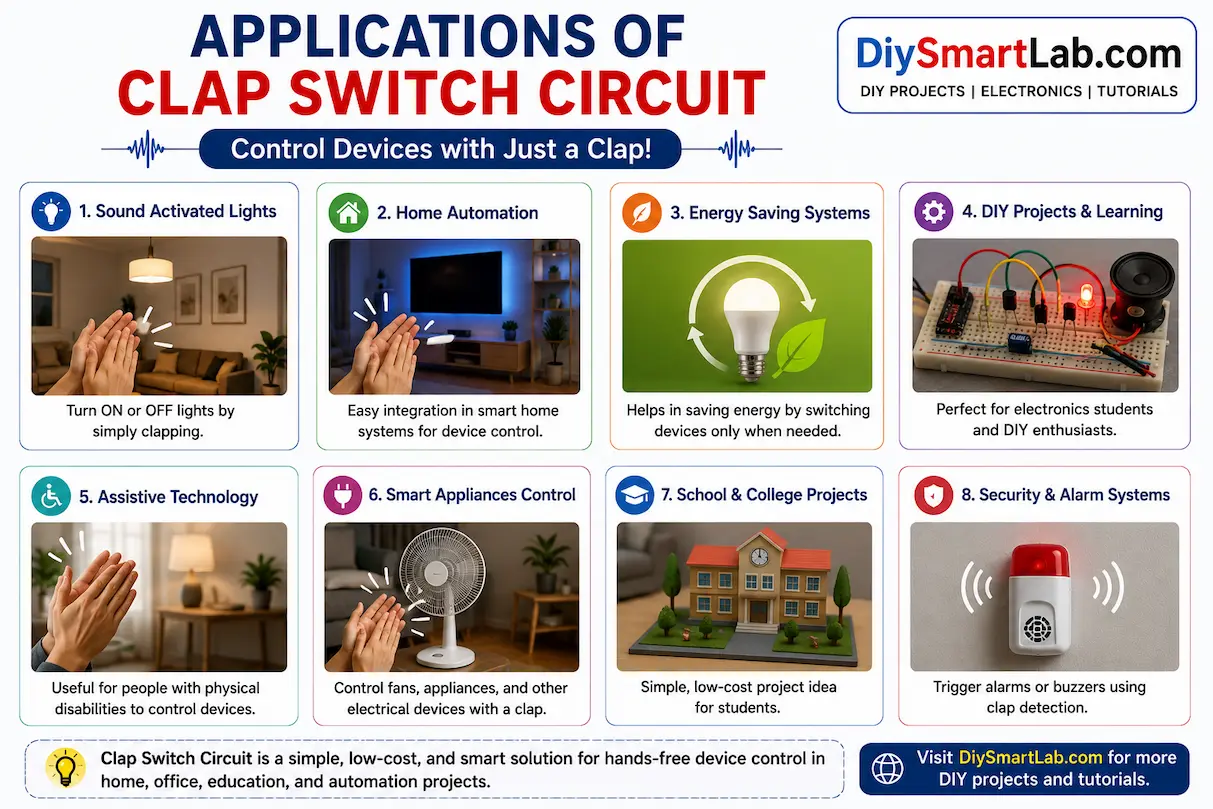
Applications of Clap Switch Circuit
- Sound activated lights
- Smart room automation
- DIY home control systems
- Assistive electronics projects
- Energy saving systems
- Arduino sound-based automation projects
Advantages of Clap Switch
- Easy to build for beginners
- Low-cost electronic project
- Useful for learning transistor switching
- Can be expanded for home automation
- Requires very few components
Limitations of Clap Switch Circuits
- Can react to unwanted sounds
- Limited sound detection range
- Basic circuits are less accurate
- Requires proper microphone placement
Safety Tips
- Use low-voltage batteries while testing.
- Do not directly connect AC appliances without proper relay isolation.
- Double-check transistor pin connections.
- Keep the circuit away from moisture.
Beginner Project Ideas Using Clap Switch
- Clap controlled room light
- Sound activated LED strip
- Smart bedside lamp
- Arduino clap automation project
- DIY home automation switch
Frequently Asked Questions (FAQs)
What is the purpose of a clap switch circuit?
A clap switch circuit is used to control electrical devices using sound signals like hand claps.
Which sensor is used in a clap switch?
An electret microphone is commonly used to detect sound in clap switch circuits.
Can I connect home appliances to a clap switch?
Yes, but you should use a properly isolated relay module for safety.
Is clap switch a good beginner project?
Yes, it is one of the best beginner electronics projects for learning basic circuit design and transistor switching.
Conclusion
The Clap Switch Circuit for Beginners is a fun and educational DIY electronics project. It helps beginners understand sound detection, transistor amplification, and switching circuits in a practical way. You can easily build this project on a breadboard and later upgrade it using relays, microcontrollers, or smart automation systems.
For more beginner-friendly electronics projects and smart DIY tutorials, keep visiting DiySmartLab.com.
You May Also Like
- What is a Transistor? NPN vs PNP Explained Simply
- What is an LED? How It Works and How to Use It
- What is a Breadboard? How to Use It Properly
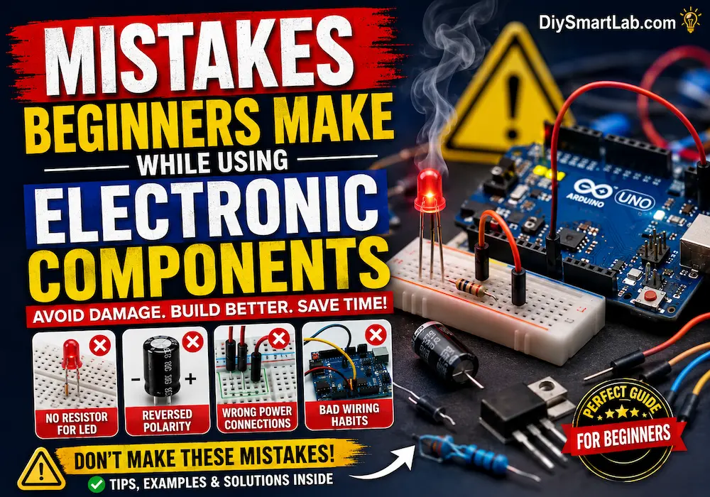
- Common Electronic Components Every Beginner Should Know
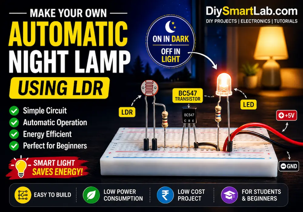
- Automatic Night Lamp Using LDR – Simple DIY Light Sensor Project
- Arduino LED Blinking Project for Beginners