What is High Level Trigger and Low Level Trigger in Relay Module? Complete Beginner Guide
What is High Level Trigger and Low Level Trigger in Relay Module?
A relay module is one of the most useful parts in electronics projects. It helps a small controller like Arduino, ESP32, or Raspberry Pi control high-power devices such as lights, fans, motors, pumps, and other appliances.
However, many beginners get confused when they see terms like High Level Trigger and Low Level Trigger on a relay module. These two terms explain how the relay input pin turns the relay ON or OFF.
In this beginner-friendly guide from DiySmartLab.com, you will learn what High Level Trigger and Low Level Trigger in relay module means, how both work, how to connect them, and which one is better for Arduino and DIY electronics projects.
What is a Relay Module?
A relay module is an electronic switching board. It allows a low-voltage signal to control a higher-voltage load.
For example, an Arduino pin gives only 5V or 3.3V output. But a home bulb or fan may use 230V AC. So, we cannot connect that load directly to Arduino.
Therefore, we use a relay module. The relay works like an electrically controlled switch.
Main Parts of a Relay Module
- Relay: The main switching component.
- Input pin: Receives the signal from Arduino or ESP32.
- VCC pin: Provides power to the relay module.
- GND pin: Common ground connection.
- Transistor driver: Helps control the relay coil.
- Flyback diode: Protects the circuit from voltage spikes.
- Status LED: Shows relay ON or OFF condition.
- COM, NO, NC terminals: Used to connect the load.
What Does Trigger Mean in a Relay Module?
In a relay module, the word trigger means the input signal that activates the relay.
This trigger signal comes from a microcontroller pin. It can be either HIGH or LOW.
- HIGH signal: Usually 5V or 3.3V.
- LOW signal: Usually 0V or GND.
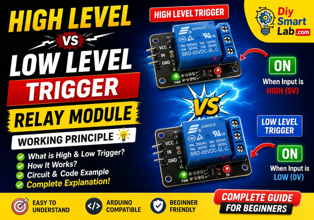
Some relay modules turn ON when they receive a HIGH signal. These are called High Level Trigger relay modules.
Other relay modules turn ON when they receive a LOW signal. These are called Low Level Trigger relay modules.
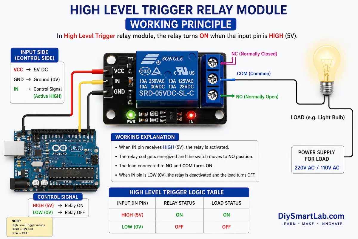
What is High Level Trigger in Relay Module?
A High Level Trigger relay module turns ON when the input pin receives a HIGH signal.
In simple words, if the relay input pin gets 5V or 3.3V from Arduino or ESP32, the relay becomes active.
High Level Trigger Working Principle
When the microcontroller sends a HIGH signal to the relay input pin, the transistor driver circuit turns ON. Then current flows through the relay coil.
As a result, the relay coil creates a magnetic field. This magnetic field pulls the internal switch contact. So, the relay changes from OFF state to ON state.
High Level Trigger Logic Table
| Input Signal | Relay Status | Load Status |
|---|---|---|
| HIGH | ON | ON |
| LOW | OFF | OFF |
High Level Trigger Example
If an Arduino digital pin sends HIGH to the relay input pin, the relay turns ON.
If the Arduino digital pin sends LOW, the relay turns OFF.
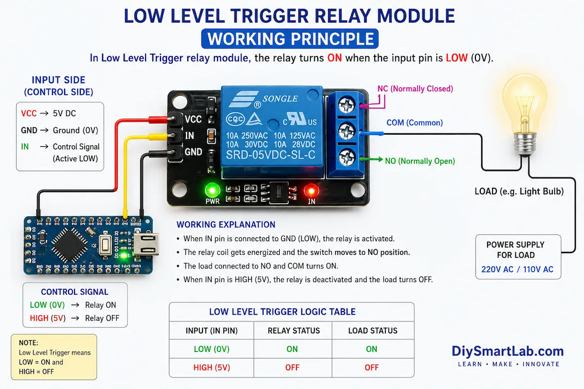
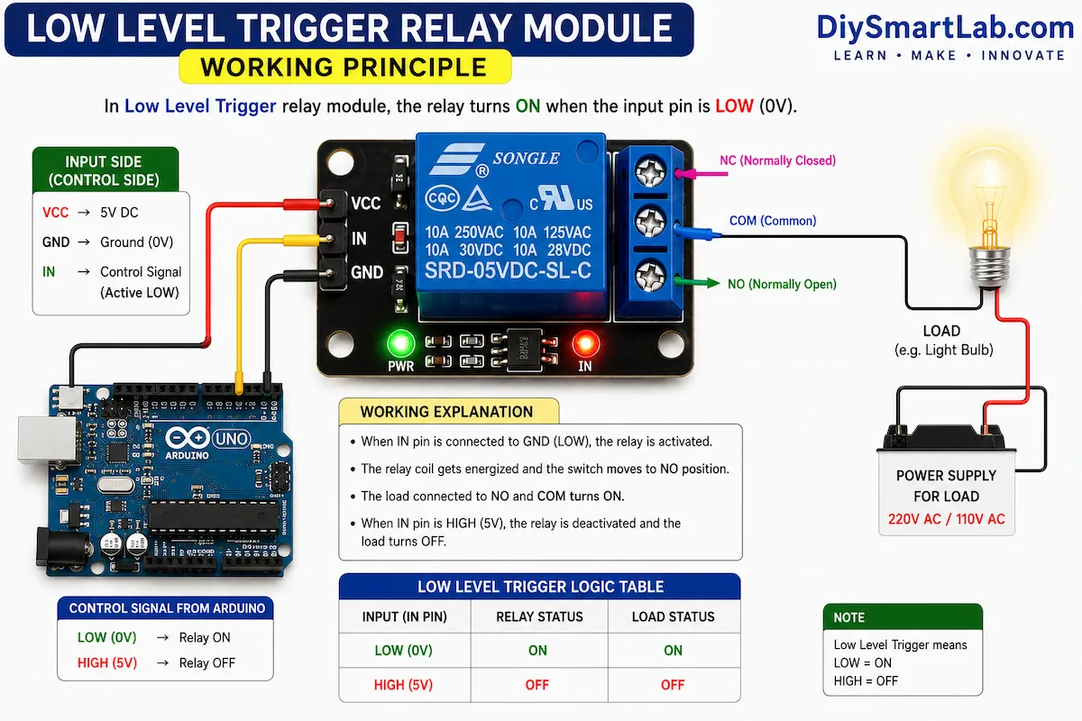
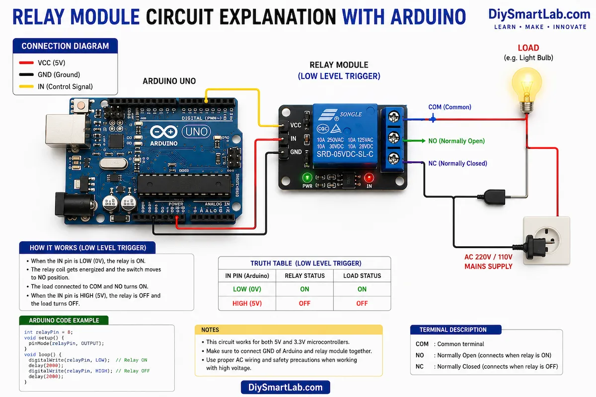
What is Low Level Trigger in Relay Module?
A Low Level Trigger relay module turns ON when the input pin receives a LOW signal.
In simple words, the relay becomes active when the input pin is connected to GND or 0V.
This type of relay module is very common in Arduino and ESP32 projects.
Low Level Trigger Working Principle
In a Low Level Trigger relay module, the relay input circuit is designed in an inverted way.
When the microcontroller output becomes LOW, current flows through the input driver circuit. Then the relay coil gets energized and the relay turns ON.
When the microcontroller output becomes HIGH, the relay turns OFF.
Low Level Trigger Logic Table
| Input Signal | Relay Status | Load Status |
|---|---|---|
| LOW | ON | ON |
| HIGH | OFF | OFF |
Low Level Trigger Example
If an Arduino digital pin sends LOW to the relay input pin, the relay turns ON.
If the Arduino digital pin sends HIGH, the relay turns OFF.
High Level Trigger vs Low Level Trigger Relay Module
| Feature | High Level Trigger Relay | Low Level Trigger Relay |
|---|---|---|
| Relay ON Signal | HIGH signal | LOW signal |
| Relay OFF Signal | LOW signal | HIGH signal |
| Input Voltage for ON | 5V or 3.3V | 0V or GND |
| Code Logic | Normal logic | Inverted logic |
| Beginner Confusion | Less confusing | Can confuse beginners |
| Common Use | Simple control projects | Arduino and automation projects |
Features of Relay Modules
- Easy to connect with Arduino, ESP32, ESP8266, and Raspberry Pi.
- Can control AC and DC loads.
- Available in 1-channel, 2-channel, 4-channel, and 8-channel versions.
- Many modules include optocoupler isolation.
- Status LED helps check relay operation.
- Screw terminals make load connection easy.
- Some modules support both High and Low Trigger modes using a jumper.
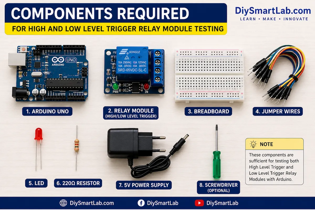
Components Required
| Component Name | Quantity | Purpose |
|---|---|---|
| Arduino Uno | 1 | Controls the relay module |
| 5V Relay Module | 1 | Switches the load |
| LED | 1 | Testing output load |
| 220 Ohm Resistor | 1 | Limits LED current |
| Breadboard | 1 | For easy testing |
| Jumper Wires | As required | For connections |
| 5V Power Supply | 1 | Powers the relay module |
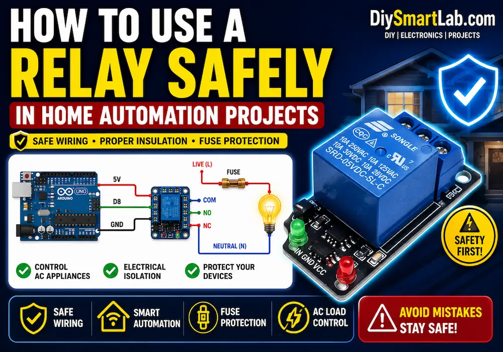
Circuit Explanation
A relay module usually has two sides. One side connects to the microcontroller. The other side connects to the load.
Control Side Pins
| Pin | Description |
|---|---|
| VCC | Connects to 5V power supply |
| GND | Connects to ground |
| IN | Receives control signal from Arduino or ESP32 |
Load Side Terminals
| Terminal | Full Form | Use |
|---|---|---|
| COM | Common | Main switching terminal |
| NO | Normally Open | Connects when relay turns ON |
| NC | Normally Closed | Disconnects when relay turns ON |
Arduino Connection
- Relay VCC to Arduino 5V
- Relay GND to Arduino GND
- Relay IN to Arduino digital pin D8
- Load positive wire through COM and NO terminal
Arduino Code for High Level Trigger Relay Module
int relayPin = 8;

void setup() {
  pinMode(relayPin, OUTPUT);
}

void loop() {
  digitalWrite(relayPin, HIGH);  // Relay ON
  delay(2000);

  digitalWrite(relayPin, LOW);   // Relay OFF
  delay(2000);
}
Arduino Code for Low Level Trigger Relay Module
int relayPin = 8;

void setup() {
  pinMode(relayPin, OUTPUT);
}

void loop() {
  digitalWrite(relayPin, LOW);   // Relay ON
  delay(2000);

  digitalWrite(relayPin, HIGH);  // Relay OFF
  delay(2000);
}
Why Low Level Trigger Relay Modules Are Common?
Low Level Trigger relay modules are common because many driver circuits use sinking current logic.
In this design, the controller pin pulls the input to ground to activate the relay. This method works well with many microcontrollers and optocoupler-based relay boards.
However, beginners must remember one important point. In a Low Level Trigger relay module, LOW means ON and HIGH means OFF.
Applications of High and Low Level Trigger Relay Modules
- Home automation projects
- Smart light control
- Fan control system
- Water pump controller
- Automatic irrigation system
- Motor control circuit
- Security alarm system
- IoT-based appliance control
- Arduino automation projects
- ESP32 smart home projects
Advantages
- Relay modules are beginner-friendly.
- They can control high-power loads.
- They work with Arduino and ESP32.
- They are low-cost and easily available.
- Status LED makes testing easier.
- They provide safe switching when used correctly.
Disadvantages
- Mechanical relay contacts can wear out over time.
- Relay modules make a clicking sound.
- They switch slower than solid-state relays.
- Wrong trigger logic can cause unexpected output.
- AC load wiring can be dangerous without proper safety.
Safety Tips for Using Relay Modules
- Always check the relay voltage rating before use.
- Do not touch AC wiring when power is ON.
- Use proper insulation for high-voltage connections.
- Test the circuit with an LED before connecting appliances.
- Use a separate power supply for multiple relay modules.
- Keep low-voltage and high-voltage wiring separated.
FAQs
What is High Level Trigger in relay module?
High Level Trigger means the relay turns ON when the input pin receives a HIGH signal such as 5V or 3.3V.
What is Low Level Trigger in relay module?
Low Level Trigger means the relay turns ON when the input pin receives a LOW signal or ground signal.
Which relay trigger type is better for Arduino?
Both can work with Arduino. However, Low Level Trigger relay modules are very common in Arduino projects.
Why does my relay turn ON when Arduino output is LOW?
Your relay module is most likely a Low Level Trigger relay module. In this type, LOW signal activates the relay.
Can I use a relay module with ESP32?
Yes, you can use relay modules with ESP32. But check whether your relay module input supports 3.3V logic.
Can I change Low Level Trigger to High Level Trigger?
Some relay modules have a jumper for trigger selection. Fixed relay modules cannot be changed without circuit modification.
Conclusion
Now you know what High Level Trigger and Low Level Trigger in relay module means.
A High Level Trigger relay module turns ON when the input signal is HIGH. On the other hand, a Low Level Trigger relay module turns ON when the input signal is LOW.
This small difference is very important in Arduino, ESP32, and smart home projects. If you use the wrong logic in your code, the relay may work in the opposite way.
So, always check the relay trigger type before connecting your load. For beginners, DiySmartLab.com recommends testing the relay module with a simple LED circuit first. After that, you can safely use it in automation projects.